As discussed in this post, the relay operating the F1 pump in the 360 is prone to failure. Later cars, as well as the Challenge Stradale, F430, and 599, use a different relay (part number 233100) rated at 50A which is more reliable. A direct swap is not possible – the two relays have different pinouts and require different sockets. This article compares the two relays and describes how to replace the socket so that the newer relay can be used.
The old relay (part number 155437) has five pins and is wired to the 360 loom in the following way (the pin numbers are stamped on the bottom of the relay casing):
- 30 (thick grey wire): Fused +12V supply
- 87 (thick red/black wire): Switched +12V to F1 pump
- 85 (thin orange wire): Switch control signal from TCU
- 86 (thin black wire): Ground
- 87a (thin black wire): Ground
The two ground connections are made through two distinct wires that end up at the same ground point on the chassis. The purpose of the two ground contacts becomes clearer by inspecting the inside of the relay, shown right below next to the 50A version.
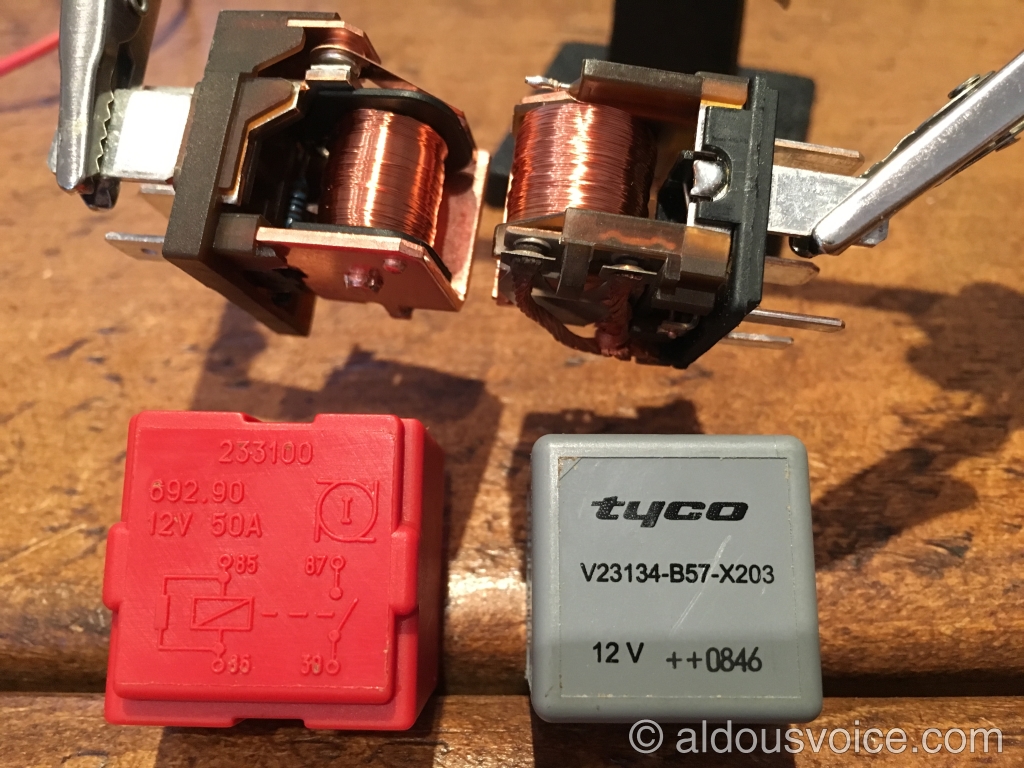
Internally, we find a resistor across the switch actuator coil (i.e. between contacts 85 and 86) which is sometimes used in place of a flyback diode. Additionally, there is a flyback diode (with threshold voltage ~ 0.8 V) across the load side of the relay, i.e. connected between contacts 87 (cathode) and 87a (anode). The purpose of this diode is to suppress voltage spikes caused by the inductive load that the relay drives, i.e. the DC motor of the F1 pump.
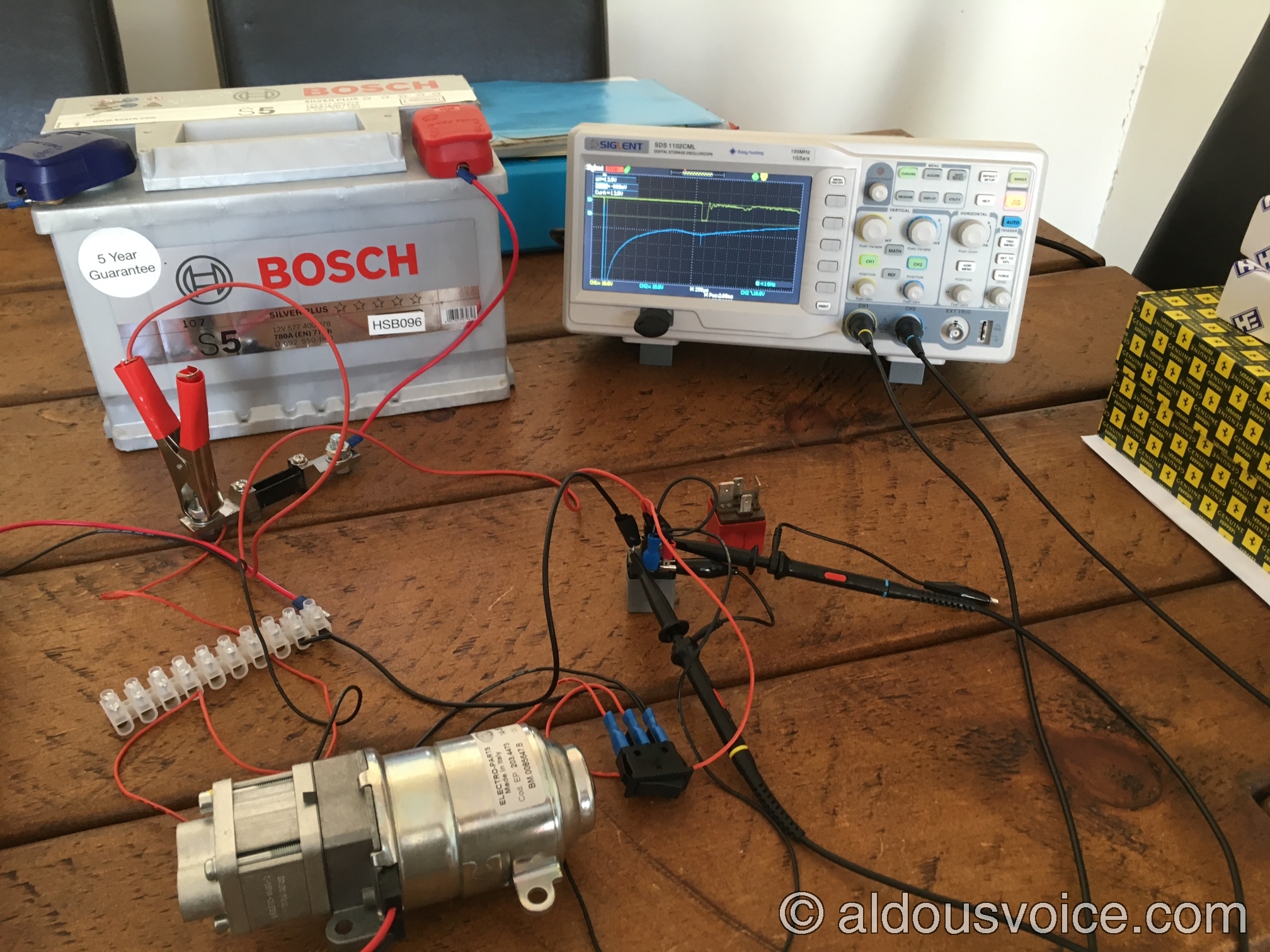
We can test how this works in practice by hooking up the relay to a battery and an F1 pump, and observing the result on a digital storage oscilloscope. In all the following screenshots, channel one (yellow trace) is connected to pin 87, and channel two (blue trace) is connected to pin 85. Triggering is set on the falling edge of channel two, to capture the moment when the relay is instructed to switch the load circuit off.
Let us first see what happens if we leave contact 87a disconnected. This negates the effect of the load-side flyback diode, so we would expect to see a (negative) voltage spike on channel one shortly after the control signal is switched to ground (with a simple rocker switch here – not representative of the output stage of the TCU so please ignore the spike on the blue trace). This is indeed what happens:
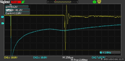
The voltage spike reaches in excess of -40V, and could be higher in a real-life scenario as in this test setup the F1 pump operates with no hydraulic load so it draws less current than when mounted in a car. Reconnecting contact 87a to ground and repeating the test above shows a very different result: the spike is eliminated, and the voltage on pin 87 only drops below ground by the diode threshold voltage, reaching at most -0.8V.
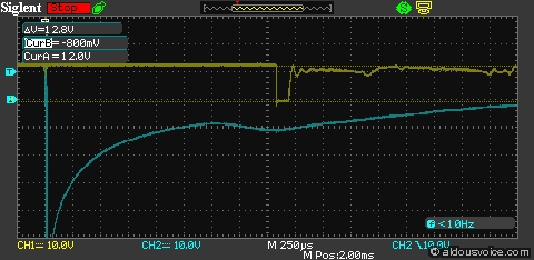
Using the same setup, we can test the newer 50A relay, which has the same pinout numbering, except for the absence of contact 87a. Like the old relay, it has a resistor connected in parallel to the switch control coil, showing a similar DC resistance across the control contacts (55 ohm vs 48 ohm of the old relay). However, there is no trace (that I could find) of a flyback diode on the load side. Surprisingly though, the negative voltage spike on the load side is quite limited, reaching less than -6V:
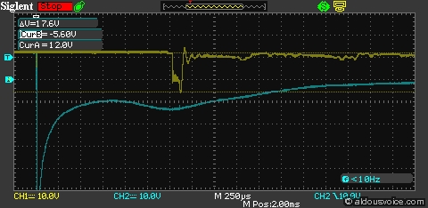
The switching time is also reduced, from 2ms to 1.5ms (this has no noticeable effect in practice).
With the previous information in mind, if you want to use the new 50A relay in a 360 which has the old version, you can proceed as follows (thanks to Mike on Club Scuderia for suggesting part of the procedure in this post). First, you will need a 70A relay holder, like this one, which costs around £5.
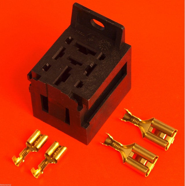
I suggest that you verify that the holder you obtain fits the new relay before proceeding any further – the new 50A relay has two 6.5mm blade contacts (control side) and two 9.5mm blade contacts (load side).
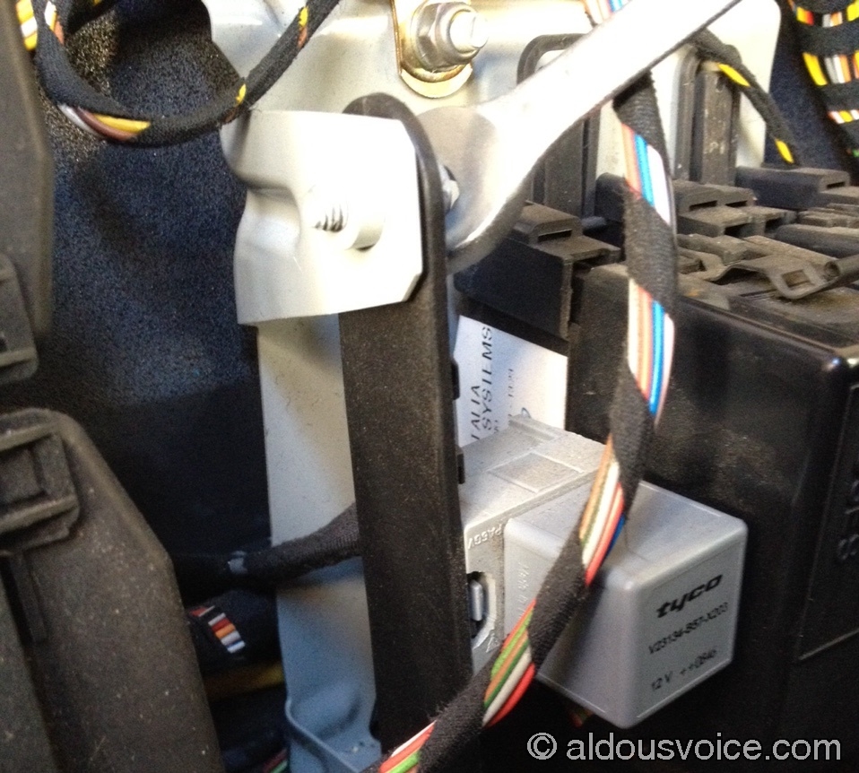
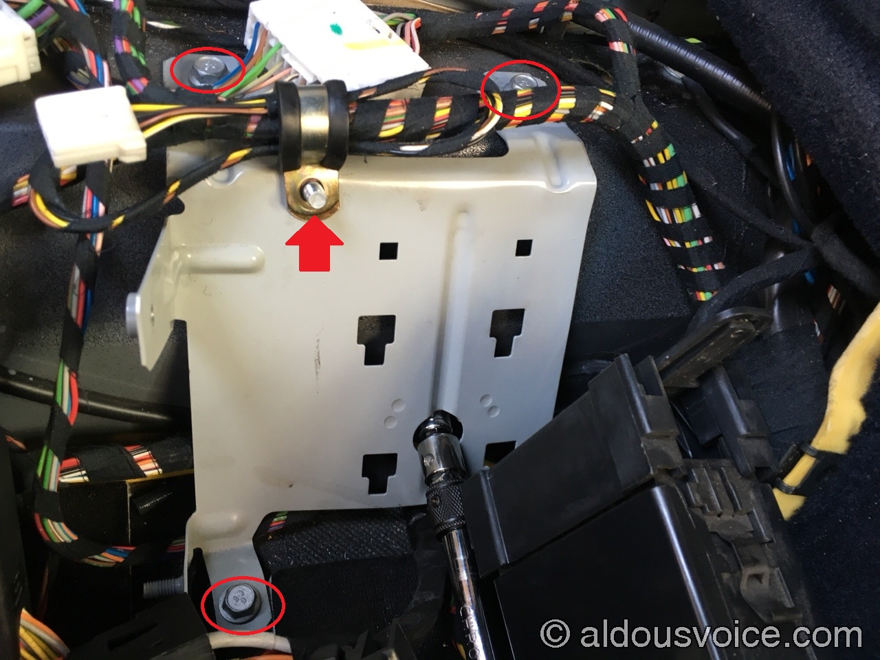
The old relay is located behind the carpet panel behind the driver’s seat (on RHD cars). Its base slots into a plastic mounting bar that is secured to the brackets of a grey metal panel by two 10mm hex head M6 screws.
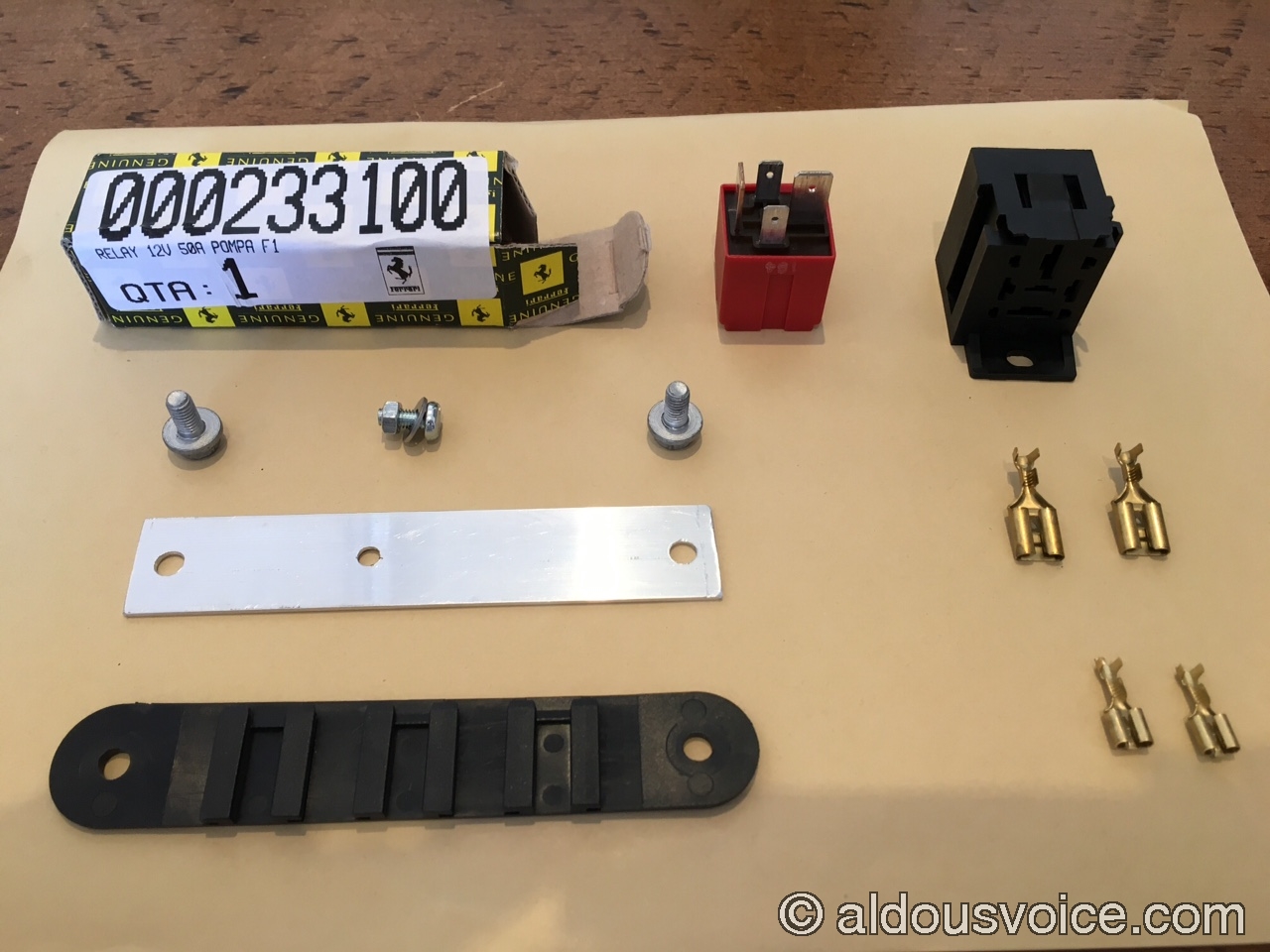
You can reuse the OEM mounting bar for the new relay base by attaching it with double-sided tape as in Mike’s post but I preferred to fabricate a new one with a piece of scrap aluminium, using the OEM one as a template.

The dimensions are 25mm by 140mm, and the M6 mounting holes are 116mm apart (centre to centre). If you are making your own mounting bar, you will also want to drill a hole to secure the new relay holder. Finally you will also, of course, need a new relay (part number 233100, approx. £5).
Before proceeding any further, isolate the power using the battery cutoff switch in the boot. Remove the relay base from the mounting bar and the old relay from the base (this may need some force):

The rear of the old relay base shows the wires connected as described earlier.

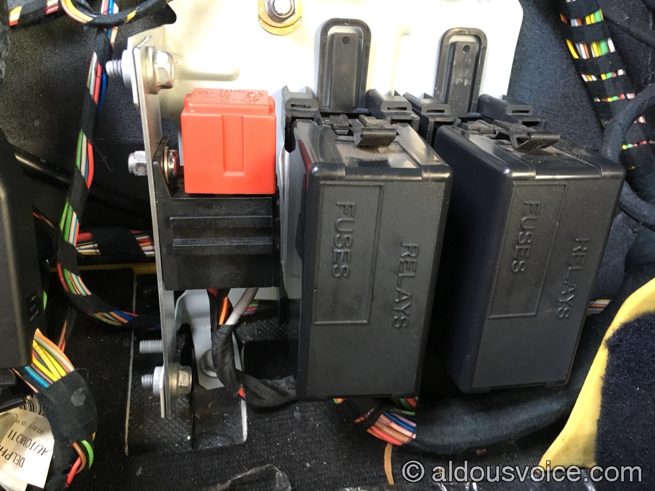
I think it is possible to remove the terminals from the old relay base but I was not able to do so. Also, you will notice that the space available to do any work is very limited – there is almost no slack in the wires. It is still possible to do the relay base conversion like this but with hindsight it is highly recommended that you remove the grey metal panel and re-route the wires, to gain some slack. To do so, you first need to unclip the two black fuse/relay holders from the panel by lifting them up and away. Then, remove the four 10mm hex head screws holding the panel to the chassis, one of which is accessible through a hole in the panel itself. It’s best to also undo the nyloc nut holding a P-clip with a bundle of wires at the top of the panel, as it will it make it possible to completely remove the metal panel.
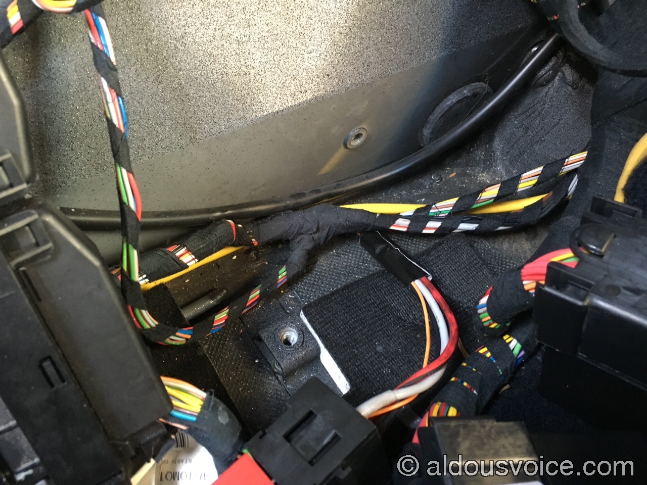
You can now route the wires leading up to the relay base under the front of the panel instead of from the side (left side, as you look at it). I chose to further protect the wires with a small length of duct tape on the section directly underneath the edge of the panel.
Now that you have enough space to work, it is time for brave pills – the old terminals need to be cut off in order to crimp the new ones onto the wiring loom. The two black wires need to be joined and connected together to the same 6.5mm terminal. The two 9.5mm terminals carry a lot of current so they need to be crimped very securely. I also protected the new connections with some colour-coded heatshrink sleeves.
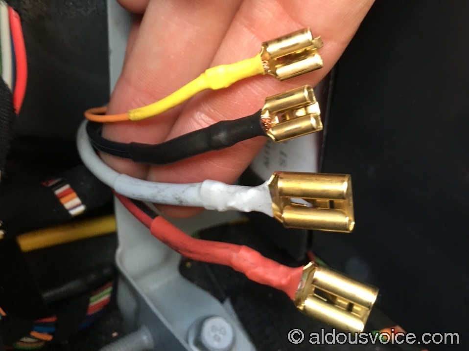
You now need to insert the new terminals through the back of the new relay base. Make sure you line them up with the correct contacts on the relay (see the table at the beginning of the post), and get it right the first time – although it is possible to extract the terminals from the base once they’ve been inserted, it’s really fiddly and best avoided. Push the terminals all the way in until you hear them click in place.
Now you can reattach the grey panel to the chassis, attach the new relay base to the mounting bar and the mounting bar to the panel, making sure there is no tension/stress in the wires. Finally, insert the new relay in the new holder.

A final note about the relay pinout. The pin numbers used by Ferrari for these relays are similar to, but do not exactly match, DIN standard 72552. One difference is that the DIN standard mandates that contact 85 be ground, and contact 86 be a positive coil driver input, while in the 360 these are reversed. Again, this makes no difference with the relays described here as they have no polarity on the coil side. Another difference is that pin number 87a is supposed to be the normally-closed contact, while Ferrari uses it as ground for the load-side flyback diode in the old relay, as we have seen. The wiring in the F430 (pictured below) is consistent with that on the 360.

Related posts:
- Ferrari F1 Clutch System
- Ferrari 360 F1 System
- Ferrari 360 F1 Pump Relay
- Ferrari F1 System Parameters
Other posts in this category: Engine and Drivetrain
If you enjoyed this post why not subscribe to this blog for further updates? Simply enter your email address in the box at the bottom of this page. Your email address will not be shared.

Hi Aldous
This and the related settings post was particularly helpful.
I’ve just had the clutch replaced on my F430 for a second time. The first occasion at 9,500 miles was because of a failed release bearing. The clutch was only some 20% worn but was replaced. A part-warranty job.
The second replacement was after another four years and 33,000 miles. In 40 years’ motoring, I have had to change only one clutch because of wear (in the V8 Lotus Esprit I had). I put this down to carefully double-de clutch/heal-and-toe downshifts.
However, the 430 had lots of city stop-start driving to and from work in Sheffield. Sheffield has lots of hills so matters compound. Perhaps under these circumstances, 33k in not bad. I also double-de clutched for spirited driving. Help or hindrance for the clutch?
Symptoms this time: the car selected gears 1 and 2, then dropped into neutral. New clutch, release bearing and flywheel fitted. Servicing and work done at Graypaul Nottingham.
I am now retired from salaried employment (now professor emeritus) so there will be far fewer city miles. Let’s see if the clutch likes the new-found circumstances.
Best wishes.
Edward
Sent from my iPhone
>
Great write-up Aldous.
A simple, cheap mod for all early F1’s. I was initially concerned that removing that second earth could spike the TCU when the relay switched but figured that the later cars used this relay anyway and if it took my TCU out I could buy a later one 🙂
The tests you’ve done prove that nothing negative happens.
M
Hi Aldous,
My pump has begun to blow the 30amp F1 fuse. The pump was replaced 5 years, 17k miles ago. I’ve removed the gray cover on the F1 relay and observed it is operating okay. I read the pressure sensor output voltage and observed the relay turns on the pump when the pressure sensor signal voltage is 2.63 volts and off when the sensor signal hits 3.05 volts. Have you encountered a situation where the pressure sensor has failed to output the correct signal voltage leaving the pump on to over work and provide excess pressure, leading to blow the fuse?
I have although it isn’t that common. For proper diagnosis you really need to connect to the tcu with an SD2 or similar
Thanks, Aldous. I will have to wait to have an SD2 session. I can replace the pump in the meantime. On the subject of pumps… someone in the US is selling a pump described as an upgrade (black aluminum casing) and a 50 amp fuse/70 amp relay combination. Does loading the circuit to that level sound okay? Have you encountered this, or a similar upgrade?