At time of first purchase, both the Ferrari 360 and F430 could be specified with an optional “Hi-Fi sound system (with subwoofer)” (code SND1) for an additional GBP 1,100 / USD 2,000. There is very little technical information available on this Hi-Fi system – its audio and electrical connections are not even shown in the 360 or F430 wiring diagrams. This article attempts to shed some light on its characteristics.
The Hi-Fi system is composed of a subwoofer enclosure, an amplifier, and uprated versions of the mid-range speakers and tweeters located in the doors, as well as an additional wiring loom (part number 200853) to connect all these parts. All the active components (i.e. all speakers and the amplifier) are manufactured by Italian company ASK Group which builds audio equipment for OEM applications for the Fiat group and many others.
The subwoofer enclosure is situated between the seats, flush against the panel that separates the cabin from the engine compartment.

It houses a 130mm dual-voice-coil subwoofer speaker (bottom aperture) and a passive resonator (top aperture), which are protected by identical metal grilles. The speaker’s two coils each have a nominal impedance of 8 ohms, and are connected to the Hi-Fi wiring loom through a 4-pin Molex connector (Molex p/n 39-01-2040 on the wiring loom side, 39-01-2046 on the speaker side), which happens to be the same as the P4 power connector on ATX PC motherboards. The red and blue wires correspond to the positive terminals of the two coils, while the black and the yellow wires correspond to the negative terminals. I have no information on the power rating or quality of these speakers, but I will note that this specific unit blew during a high-volume in-system test and that the ~£100 price that Ferrari itself charges for it is suspiciously low (the door 160mm midrange speakers are even cheaper, at less than £50 each).

The amplifier is located inside a leather-finished cradle which sits underneath the central part of the dashboard, directly below the head unit. It should be noted that the coupe and spider tipos have different part numbers for the amplifier, but I have no reason to believe that they be significantly different (the other components are the same). However, for the avoidance of doubt, this article examines the spider version.

The cradle is held in place by two short metal rods protruding from its back, which slot into support holes in the bulkhead, and is secured by a single Phillips-head self-tapping screw which screws upwards into the bottom of the dashboard through a hole in the leather. In order to remove the cradle from the cabin, the 26-pin connector at the back also needs to be detached.


The cradle has metal grilles on its bottom side and on its right-hand side (when viewed from the top) to aid ventilation. The amplifier can be removed from the cradle by undoing the four M4 Phillips screws that hold it to the cradle metal frame.

The amplifier enclosure is aluminium with a steel cover, and measures 203mm by 135mm by 55mm (LxWxD) excluding the metal flanges and the green connector housing, the latter of which adds another 21 mm to its length. It weighs 1.32 kg and its build quality appears solid but it is let down by the fact that all its screws (both internal and external) crudely self-tap into the grooves of the aluminium enclosure. Removing these gives access to the internal components.


The core of the device is four TDA1562Q monolithic amplifier ICs, which are rated at 70W @ 4 ohm each, albeit with a substantial 10% of total harmonic distortion (THD) at peak power. These are held firmly against the wall of the enclosure (which acts as heatsink) with clips and heat-conducting paste.
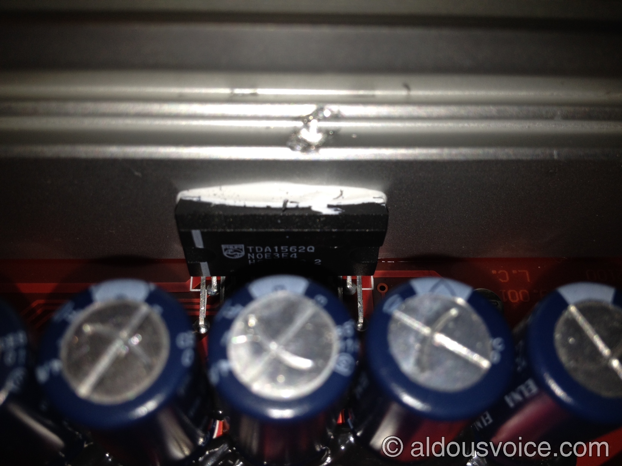
The rest of the PCB is taken up by the passive components needed by the ICs (mainly large electrolytic capacitors – see p. 14 of the datasheet) and a few operational amplifiers, presumably part of an active filter (more on this later). This is the extent of the information that can be gathered by visual inspection – what follows was obtained with measurements and tests on this specific unit.
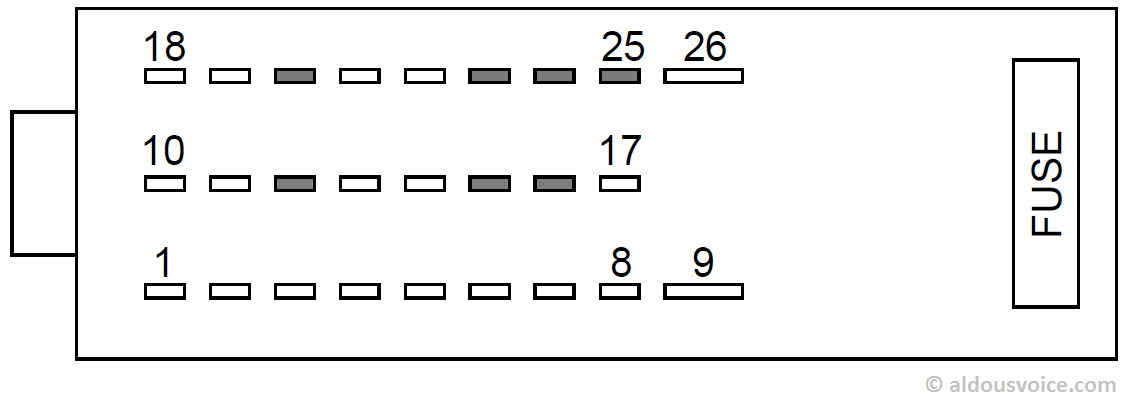
The first thing to determine is the pinout of the connector. I was not able to identify if this is a standard connector type, so I have to assume it is a proprietary design by ASK Group (if you recognise it from elsewhere, please do let me know). The amplifier side has 26 spade-type male pins arranged over three rows, numbered as in the schema below. 24 of three pins are 3mm wide, while two of them (no. 9 and 26) are 6mm wide.
The wiring-loom side is connected to the rest of the system as follows:

In essence, the amplifier receives the four pre-amplified channels (front and rear, left and right) from the head unit, amplifies them further (hence it is sometimes referred to as a ‘booster’), and drives the door and subwoofer speakers. Presumably this is possible as the Hi-Fi wiring loom probably intercepts the union of connectors 42D and 43D, which are normally connected to each other in a car without the Hi-Fi option (where the head unit drives the door speakers directly).

Further investigation reveals that the right- and left-hand side door speakers are driven independently (i.e. using two separate ICs) by the amplifier, using the front right and front left channels from the head unit as inputs, respectively. Incidentally, it should also be noted that there is only one pair of audio wires going into each door, which is used to drive both the mid-range speaker and the tweeter, with no crossover in between. On the other hand, the amplifier drives the two coils of the subwoofer speaker independently, but it uses the average of the rear right and rear left channels from the head unit as inputs, which means that the two coils are driven by identical signals.
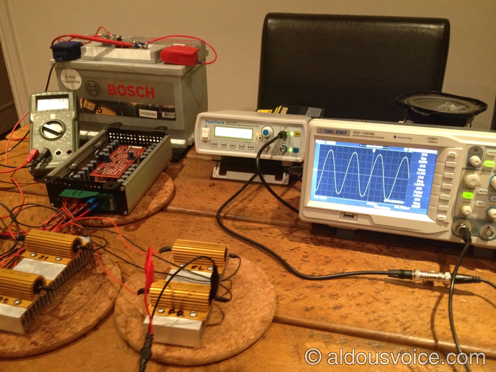
In order to test the performance of the amplifier the following setup was built:
- a fully-charged Bosch S5 battery as power supply
- both a 12 MHz function generator and an iPhone with a function-generator app as signal input
- a 100 MHz digital storage oscilloscope (DSO) as measuring equipment
- four 4.7 ohm, 100W, wirewound power resistors mounted on aluminium heat sinks as dummy loads
- a Becker Traffic Pro BE6100 head unit as pre-amplifier when the iPhone signal was used
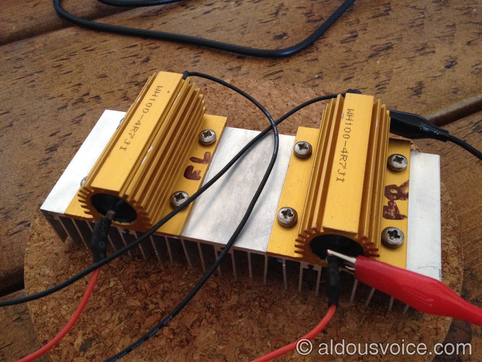
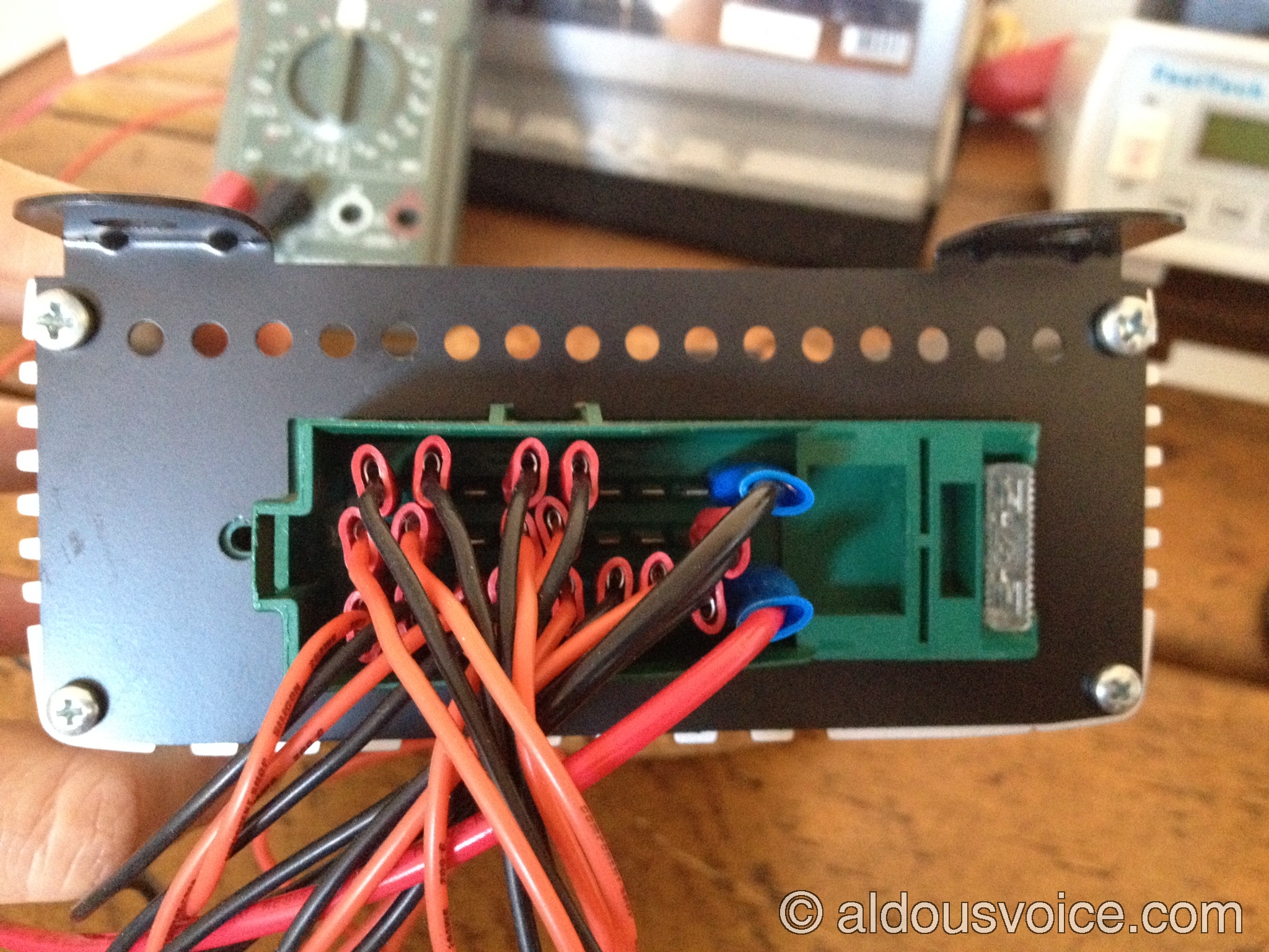
The amplifier was connected to its signal source and to the dummy loads using individual female spade connectors, as shown in the photo below.
The first test was to determine the frequency response of the four channels of the amplifier. As above, the two subwoofer channels use the same average signal as input, so it was no surprise that they have identical frequency response. They also appear to have a band-pass filter peaking at 62 Hz, with approx 50 dB/decade slope on both sides and -3 dB points at 21 Hz and 173 Hz.

On the other hand, the frequency response of the two front channels, apart from a common high-pass filter at 31 Hz, appear neither identical nor particularly flat. The test was repeated with two separate signal sources, with and without the head unit, and the data was confirmed in all cases. It is also interesting to note that the high-frequency roll-off does not happen until well past 1 MHz (way beyond what the human ear can respond to).

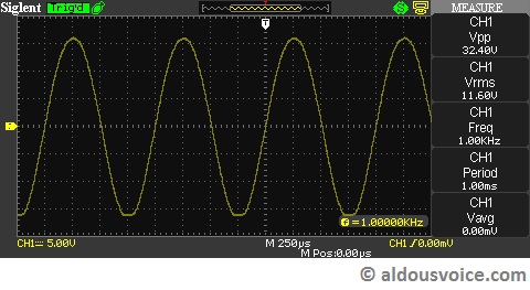
Another test worth performing is a measurement of the max output power the amplifier can operate at. This was done by using a sine wave as input and increasing its amplitude until the output of the amplifier, measured across the load resistor and viewed on the oscilloscope, started to distort or “clip”. At that point, the output power on that channel is given by the square of the root-mean-square (RMS) amplitude of the output wave, divided by the load resistance value. As we’ve seen in the plots above, the amplifier gain is frequency-dependent on all channels, so the maximum power will depend on the frequency. For the purpose of this test, the front-right channel was used, with a frequency of 1 kHz (where the two front channels happen to have identical gain). The measured amplitude was 11.6 V (RMS), which gives (approx) 28 W of peak output power per channel. Below is a snapshot from the oscilloscope with the output wave starting to distort (evidenced by the bottom of the wave starting to square off).
A few caveats need to be given around this measured value. First of all, a real loudspeaker with a nominal impedance of 4 ohms would draw more current than our test 4.7 ohm resistors. Secondly, although care was taken to perform the measurement with the resistors in “cold” state, they do heat up very quickly at peak power (hence the heatsinks) and resistance increases with temperature, which was not factored into the measurements above. Lastly, and perhaps more importantly, the supply voltage here was not regulated, and dipped as low as 12.2V under heavy load. This is representative of a car with its engine off, but lower than you would have in a car with the alternator running – measuring output power in that setup would have probably yielded a higher value.
Related Posts:
Other posts in this category: Interior
If you enjoyed this post why not subscribe to this blog for further updates? Simply enter your email address in the box at the bottom of this page. Your details will not be shared.

Nice write up, Aldous. Very technical and good explanation. I would like to make some comments based on my experience replacing the entire sound system.
First, without the benefit of electronic testing equipment, I had to make a judgement based purely on how the original system sounded. In a word … it sucked. Replacing the sound system was the first change I decided to make on my car.
My review of the components is less kind than yours. Firstly, what Ferrari calls a sub-woofer is not a sub woofer. The enclosure is much too small and the woofer they installed has a very low capacity to drive heavy base. The only manufacturer I could find with a small woofer that even comes close to being in sub-woofer class is Focal. They are pricey and I installed two of them. They work nicely, but the frequency response in that small enclosure only gets down to 50Hz … not exactly sub-woofer class due to the small enclosure. But better than OEM.
Another disappointment was the Becker head unit. The only redeeming value it has is that it says “Ferrari” on it. Every other aspect from the human ergonomics to the features are sub par. I decided to replace it with an Alpine unit, but there are many high quality choices.
My 360 came with a CD disc change. I threw that out in the trash bin as no one uses CDs anymore. My Alpine unit has a CD player (that I never have used) and an USB port which is where I plug in a USB drive with all my tunes. I ran the USB connector to inside the glove box.
I put a nice new Hertz amp in the spot previously occupied by the CD changer. Perfect fit and place a 6″ x 9″ oval metal grill over the opening I cut in the panel to allow ventilation and to gain access to adjust the amp should the need arise.
I used the old amp cradle to house the two cross-over circuits for the new door speakers.
Speaking of door speakers … the Ferrari OEM door woofers and tweeter were also very low quality. One could easily purchase a replacement set of similar quality for less than $25 a pair (woofer and tweeter). I replace the door speakers with speakers from Hertz. I sized the speakers to minimize any mods required to make them fit. I then discovered that Ferrari only ran speaker wires to inside the door panel. The same wires feed both the woofer and tweeter. The tweeter had a small cross-over circuit in the back side to filter the bass out. The woofer received all signals. Running new speaker wires to the new door speakers was challenging. It required drilling a new hole in the edge of the door just over the existing mufti-pin plug. Routed the new wires through the existing rubber wire loom and then into the new hole. A rubber grommet and some additional cable looming material made for a very neat installation. The new wires used are 14AWG replacing the existing Ferrari 22AWG wiring. Much better to carry higher current load and drive the new speakers.
The end result after gutting the existing system, pulling out the dash and contorting myself to get to all the wires and such was very satisfying. The new system sounds great. Anyone who like to listen to music should consider trashing the existing sound system in their 360 or 430. Don’t know how good later Ferrari’s are with sound systems, but the 360 / F430 definitely did not put quality into their sound systems.
Steve
I’m very impressed with the amount of detail concerning the Ferrari audio system, is there no end to Aldous’s talent?
I’ve replaced my head unit with the Alpine 511 motorised touch screen, SatNav, handsfree phone and rear camera. I’ve kept the Becker in case I sell the car, which strangely is the same unit as used by Porsche with just a name change and a rubbish sound system – what is it with Germans and rubbish audio? – too much Wagner??
The next upgrade will also be the speakers and I’ve decided to go with an Audison Bit 10 installation, which happens to be Italian ( a pity that Ferrari didn’t speak to them!), I had demo’s from a “Four Master” and the sound is the best that I’ve ever heard in a car – but it’s quite expensive, the system that I’m saving for is in excess of £2000 and that’s considered to be an entry level option.
Have you got any more info on those speakers? I’d be interested to know if they fit without any modifications.
I don’t have the actual specifications, I would recommend a visit to a “Four Masters” store, “Four” is the importer of the Audison products and the “Masters” are a select number of approved installers, the “Bit 10” and their other processors have to be set up by using microphones inside the car to enable the system to be tuned.
My local Four Masters is Accutek near Winchester.
Great article as always.
I can add a little more knowledge. My F430 spider has the ludicrously overpriced Bose add on system. The system seems OK and as I didn’t pay for it I am sort of Ok with that. I changed the head unit though to a Clarion NZ502e with very little hassle at all.
The guys at Ultimate Audio in Bromsgrove did it for not much money and managed to get everything working. The sound quality is much better, the SatNav a hundred times better than the crappy Becker and the sound button in the centre console for roof up/down works and it is compatible with the iPhone.
I’ve connected the iPod via the glove box and to be honest I can’t say that there is anything bad about it apart form the air vents are in the way of the screen and it doesn’t always auto open/close which seems to be a Clarion issue.
John
>
A very interesting debate is going on here. I am seriiously considering a F430 spider, but obviously apprehensive of the sound system and the lack of current technology. I can now understand how every review I have read continously states that you do not need a sound system with a symphony orchestra behind your ears. It is now apparent they are making excuses for an overpriced sound system they have promptly turned off after hearing a couple of quavers that they were not expecting.
Considering it would be difficult to maintain 6000 rpm for more than 15 minutes on the roads in the UK, then surely an owner of such a car would want to be self-indulged in a pillow of clouds luxury.
Hi Brian
I’m not quite sure what your query is?
Hi Aldous Voice, I recently upgraded the HiFi stereo system on my 2006 F430 Spider. I cant thank you enough for all the information you shared here. It sure made my stereo upgrade much much easier.
Thank you very much for sharing your great knowledge. Sincerely appreciated.
Dan L.
whatheheck