The Becker radio head units installed in Montezemolo era Ferraris (think 360, F430, 575, 599, etc) are known to develop a fault whereby they draw a substantial amount of current even when in OFF state. This article explores a possible cause for this fault and proposes a simple (although not perfect) workaround. For info on tracking down the source of a current drain see this post.
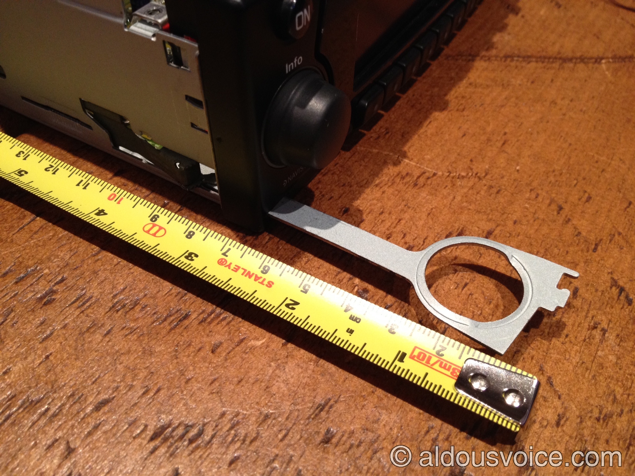
As described here, Becker head units can be extracted by unlocking the retention mechanism with two keys. The two keys only need to be inserted approximately 3 cm to engage the mechanism, as shown in the photo below.
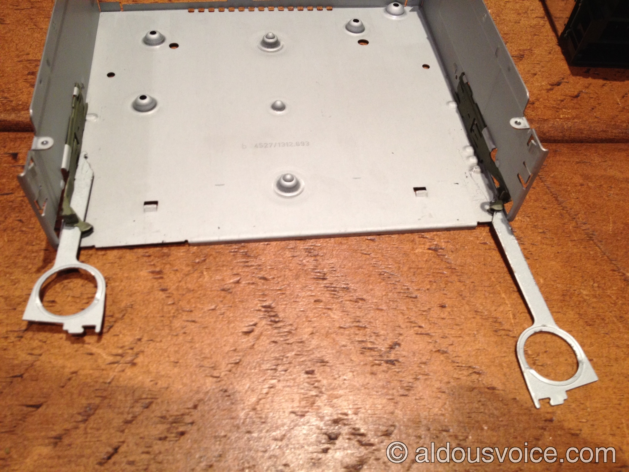
However, the layout of the head unit chassis is such that, with very little force, the removal keys can be pushed all the way in. This is shown in the photo below, where one correctly-engaged key is compared with a fully inserted one (shown with the head unit core electronics removed from the chassis, for clarity).
When this happens, the tip of the left-hand side key ends up directly below the IC with the silver casing shown in the photo below (another key is shown in proximity to illustrate how far its tip can reach).
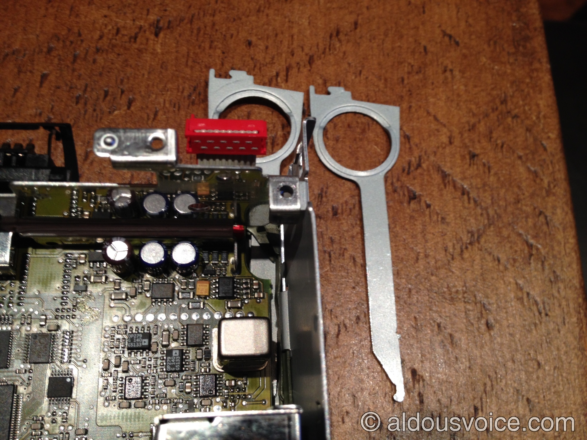
This IC is an EWTS82NN – a very clever piece of electronics known as an angular rare sensor, which detects changes in the direction of motion though the Coriolis force that acts on a vibrating tuning fork, and is part of the head unit GPS system. Crucially for us, this IC is soldered with its pins protruding out of the bottom of the PCB, as shown in the photo below:

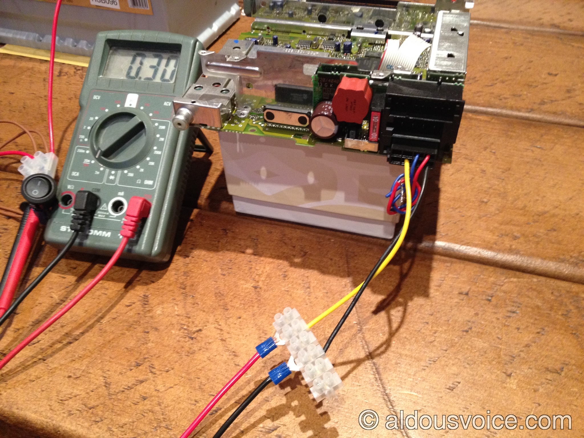
The pin closest to the front of the head unit (circled in red in the photo above) is pin 4, which is permanently connected to a +5V supply even when the head unit is off. Inserting the left-hand removal key all the way in is almost guaranteed to short this pin to ground, which is why it is of paramount importance to switch the battery isolator switch to OFF before attempting to remove the head unit. Shorting this pin to ground will not blow any fuse as the +5V is likely obtained from the main +12V with a DC-to-DC converter, most of which have built-in overload protection. However, other components could be damaged by the current surge and there is strong circumstantial evidence that the reported anomalous current draw that affects these units develops after such a short. When this fault develops, the head unit will appear to work perfectly in all its functions, but it will draw hundreds of mA even when in OFF state. A damaged unit is shown below, with a current reading (when off) of 300mA. Such a high current draw equates to more than 50 Ah over a week and can flatten even a healthy battery if not connected to a battery tender.
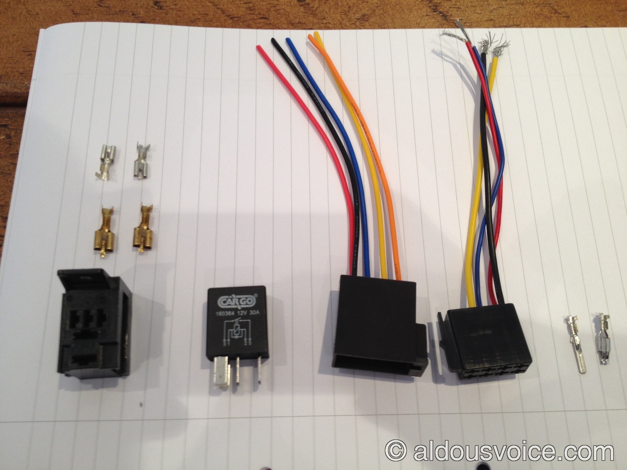
I am not aware of any way of fixing this fault once it develops, but an inexpensive workaround is possible, although it is not without drawbacks. The idea is to intercept the permanent +12V supply to the head unit, which corresponds to pin 4 on connector A, and insert an SPST (normally open) relay to control it, driven by pin 7, which is only live when the ignition is on. An ideal candidate for the relay is the HC Cargo 160364 like the one used in the Remote Control Luggage Compartment Opener circuit. You will also need both a male and a female ISO 10487 type “A” connector, which can easily be bought from car audio suppliers, often pre-wired. Here is a photo of a set of components for this project:
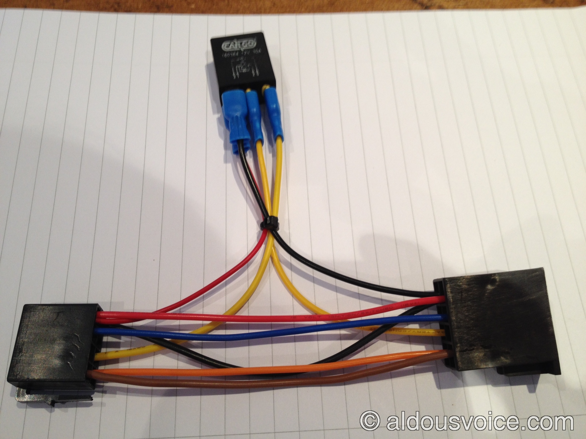
You will now need to make connections between the male connector and the female connector for the following pins, on a one-to-one basis: pin 8 (ground), pin 7 (ignition-driven positive), pin 5 (power supply for, among other things, antenna preamplifier), pin 2 (reversing light signal), and pin 1 (speed signal). Pins 3 and 6 have no connection in the car wiring loom so they are not needed. You will also need to connect an additional wire to pin 8 (either male or female side) and link it to pin 2 (also referred to as pin 85 in ISO relay sockets) of the relay, as well as an additional wire to pin 7 (either male or female side) and link it to pin 1 (also referred to as pin 86 in ISO relay sockets) of the relay. Wires attached to pins 4 on the male and female side must not be linked together, but rather connected to pins 3 and 5 (also known as 30 and 87) of the relay. The finished circuit looks like the one below, where female spade connectors were used to connect to the relay rather than a traditional relay holder.
This simple circuit can now be inserted between connector A of the car wiring loom and the head unit, and will result in the head unit being powered only when the ignition is on. This will ensure that it draws no current when the car is off. However, as anticipated, there are some drawbacks with this solution: the head unit will lose all its settings (eg radio presets) when it powers off, and you will need to enter the security code each time it is powered back on again.
So far I have only examined a Becker Traffic Pro that has developed this fault. Clearly, non-navigation equipped Becker units do not have the IC noted above but they can suffer from the same current draw when switched off. If anyone has one of these faulty units I would be very interested to examine it to see if the fault could have been caused by the improper use of the removal keys.
Other posts in this category: Interior
If you enjoyed this post why not subscribe to this blog for further updates? Simply enter your email address in the box at the bottom of this page. Your details will not be shared.
