The way the 360 is set up, releasing the luggage compartment bonnet is a little awkward. The key needs to be in the ignition and the switch is in the centre of the car – not so bad if you’re in the car but from outside opening up can be a chore. There is the option of using the manual release but this really should only be for emergencies as there is a risk of breaking the cable. Note that the F430 was improved a little by having the switch located by the door which can be operated without the need for the ignition to be on.
When I had a 360 I planned to fit a remote control unit to operate the bonnet but the accident put paid to that idea. I did discuss the concept with a friend and we sketched out how it could be done. I cannot take much credit for this – what you read forward of this sentence is his work….
A feature I always found very annoying in the Ferrari 360 is that in order to open the bonnet to access the front luggage compartment you need to unlock the car, get in, turn the ignition key, and operate the bonnet switch in the central console. As it turns out it is possible, with a few inexpensive components, to build a radio-operated device that opens the bonnet via a remote control.
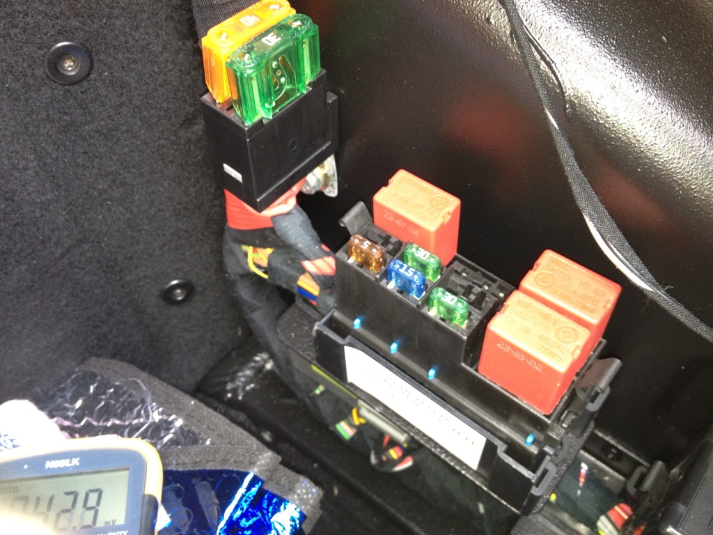
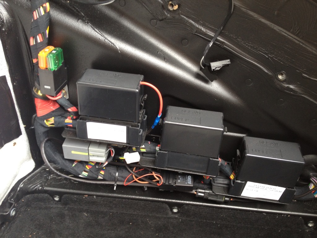
The bonnet opening mechanism consists of a solenoid that, when energised, pulls the catch in the bonnet lock. The solenoid is driven by an SPST normally-open (or “Form A”) 30A relay in the rearmost fuse holder in the front luggage compartment (relay no. 26), protected by a 30A “mini”-size fuse (fuse no. 10). Here is a picture of the fuse box with the bonnet relay removed:
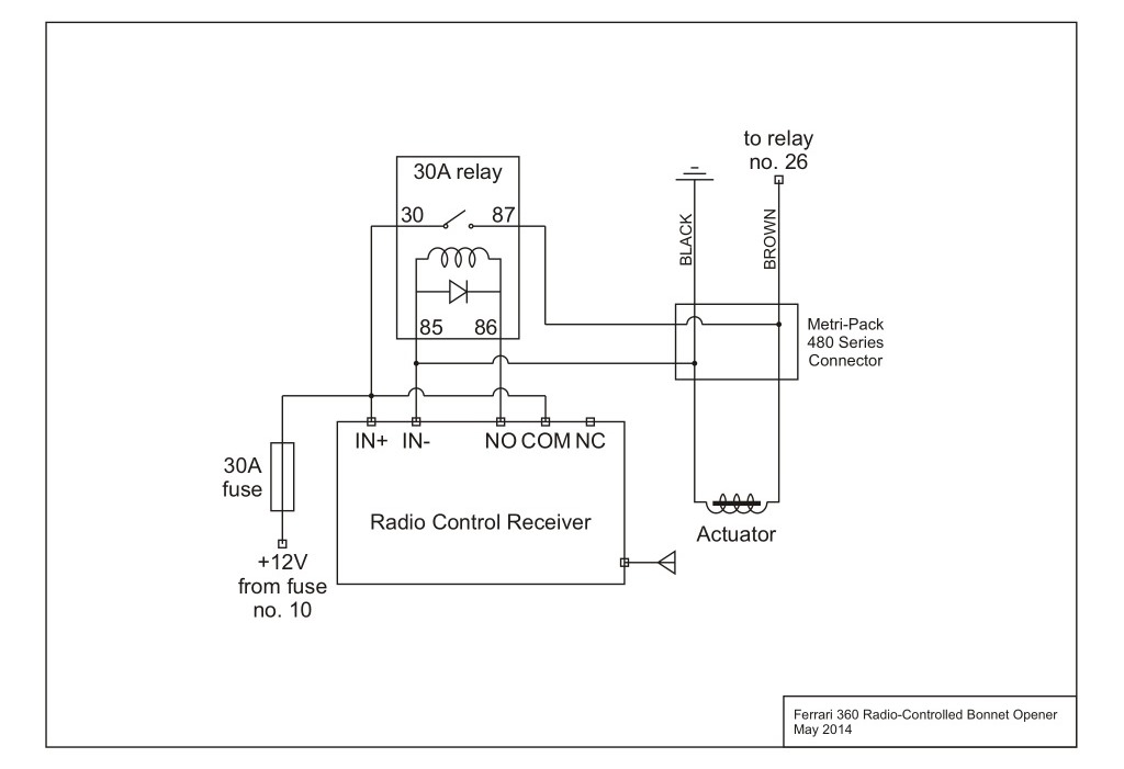
The aim is to build a device to drive the solenoid independently of, and with as few modifications as possible to, the existing wiring. This is the circuit diagram of the device we want to build:
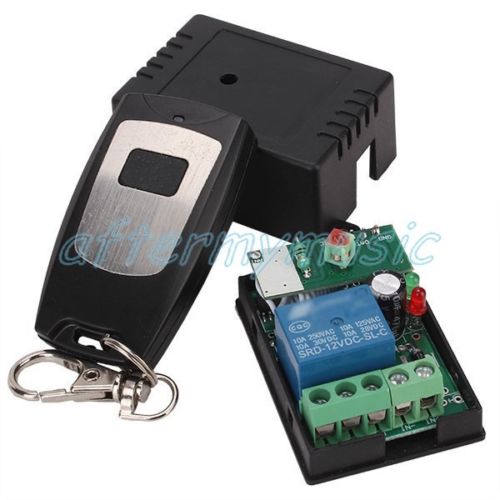
The core of the device is a wireless remote control switch like this which can be bought for less than £5. If the link breaks in the future you are looking for a 12V remote control unit which operates on a Jog Mode. ie: when the button is pressed the relay contacts are made and when the button is released the relay opens. This is also called a momentary switch and is needed since the solenoid only requires a short pulse of power to release the catch.
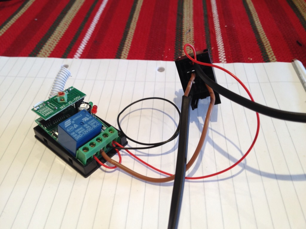
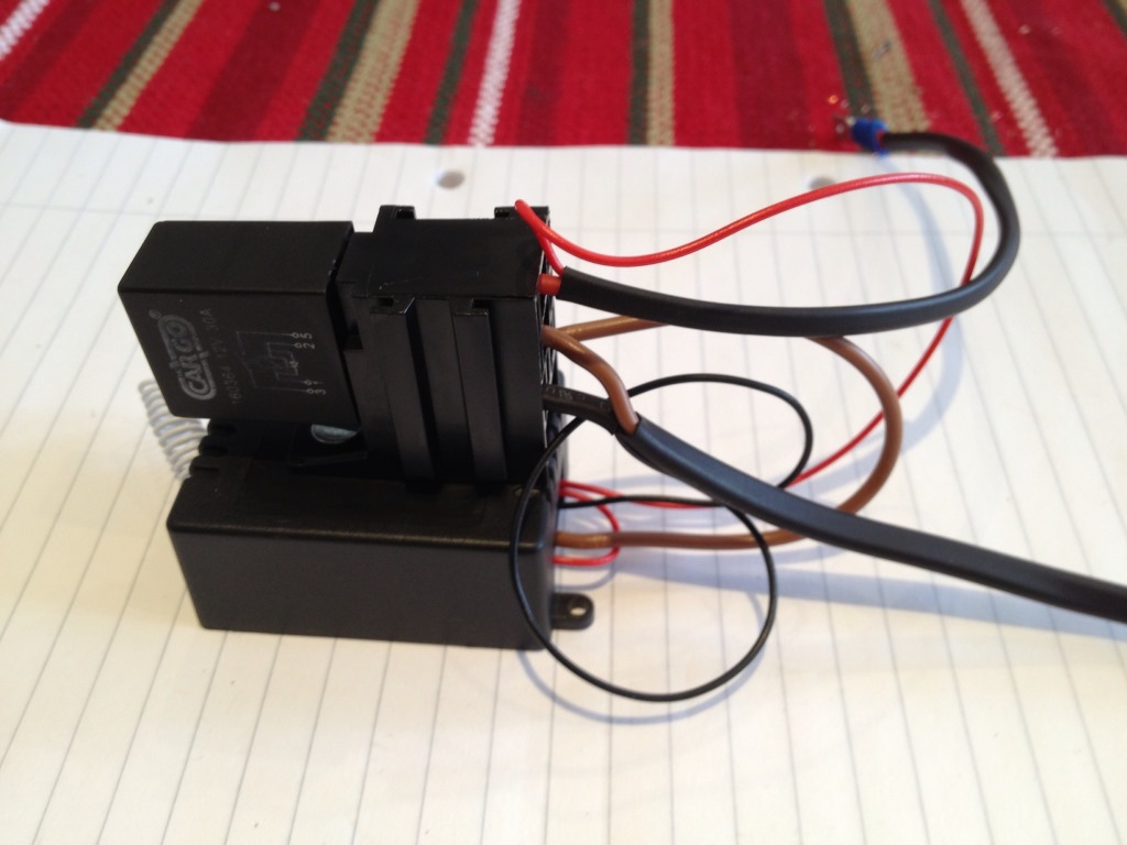
The solenoid can draw in the region of 25A so this switch cannot drive it directly – a slave 30A relay needs to be added, preferably one with an internal flyback diode such as the HC Cargo 160364 or the Durite 0-727-13. If you use one of these you will also need a relay holder of “micro” size, like this. They normally have the standard pinout numbering stamped on them according to DIN 72552 which are indicated on the circuit diagram above as well. Here are two photos of the radio control unit wired to the relay holder as in the circuit diagram above:
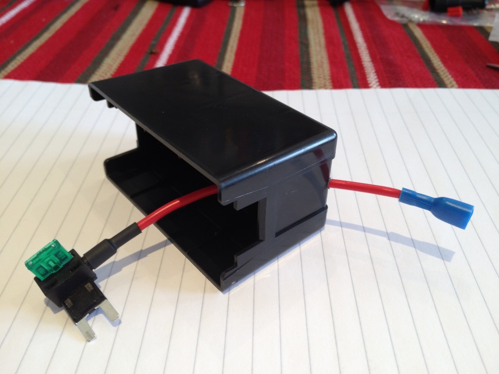
Two further issues need to be addressed now: how to safely power the device, and how/where to intercept the solenoid control. A 12V supply which is live even with the ignition off and the bonnet closed is available at the previously-mentioned fuse no. 10. This can be accessed using a “fuse tap” device like this one. It inserts in place of an existing fuse and has two fuse sockets: one for the original fuse that was removed, and one for a new fuse that links the original connection to a lead that can be used to power additional devices, like ours. I drilled a 3.5mm hole in the fuse box cover to allow this lead to escape and crimped an insulated female spade connector at the end of it (shown with only one 30A fuse: for our purposes, two 30A fuses will be used here):
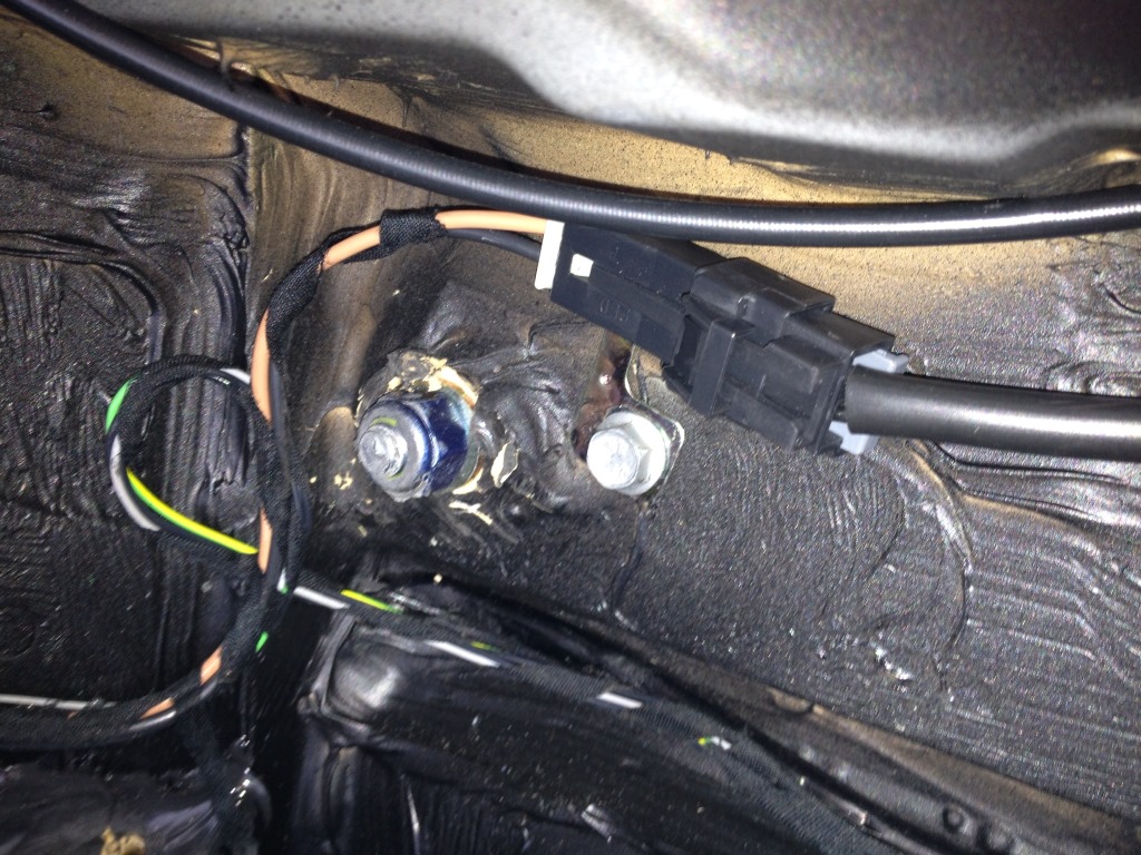
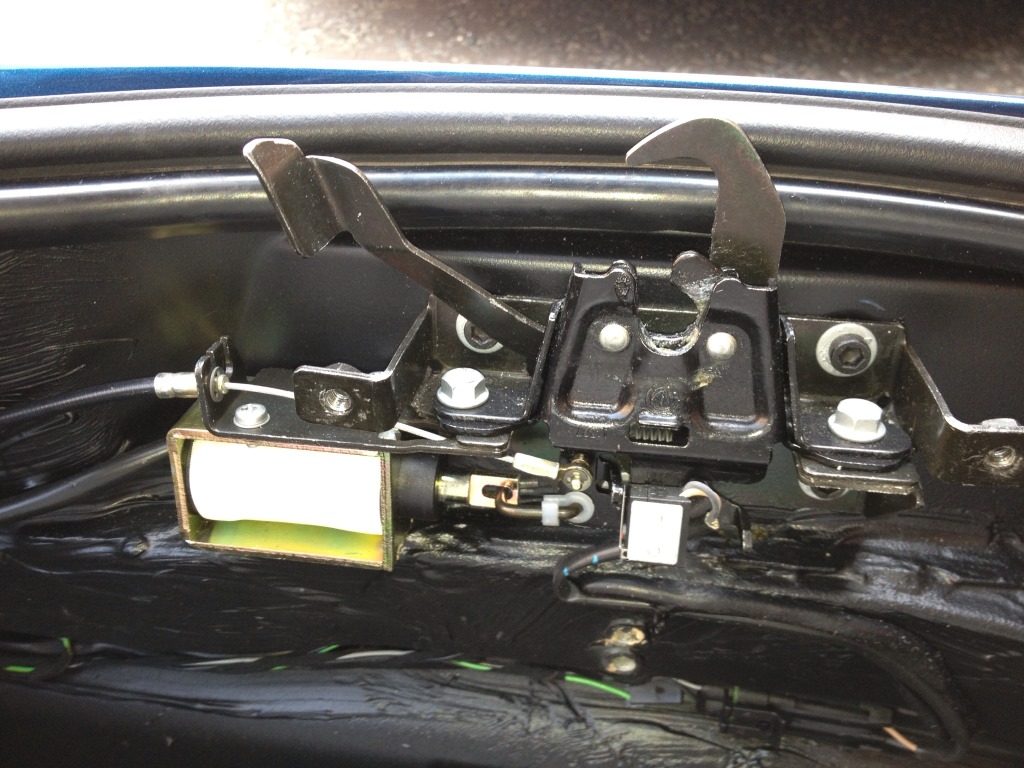
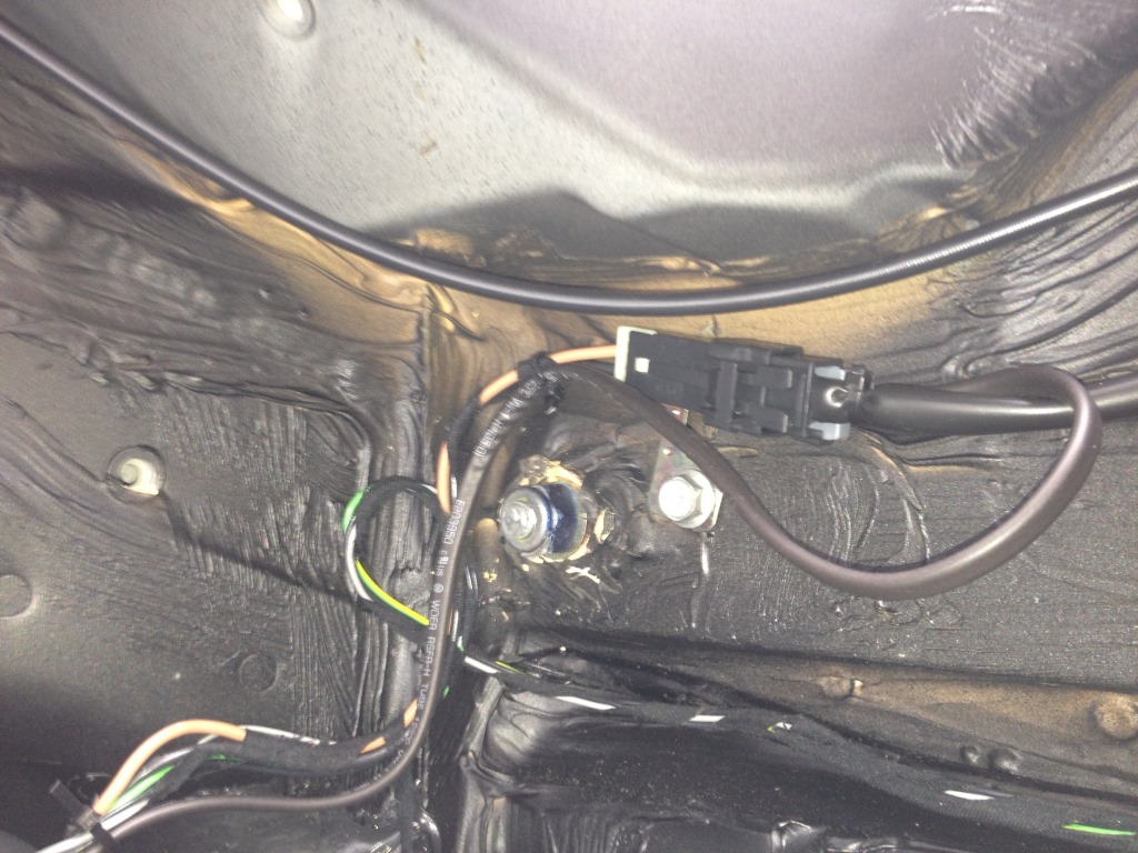
The other issue is how to intercept the solenoid control. The solenoid is connected to the loom/fuse box with a Metri-Pack 480 Series 2-way connector, which is anchored to the bulkhead near the front bumper retention bolts:
An ideal solution would be to obtain an additional male & female Metri-Pack 480 and use them to connect our device to the original connectors at this point. However these are very hard to find in Europe so I opted for disassembling one of the existing connectors and connecting additional wires to it. I chose to wire into the solenoid-side (female) connector for two reason a) the solenoid can be easily removed from the car, which makes working on it easier, and b) any mistake would not have dire consequences since a new solenoid is only about £30 to buy.
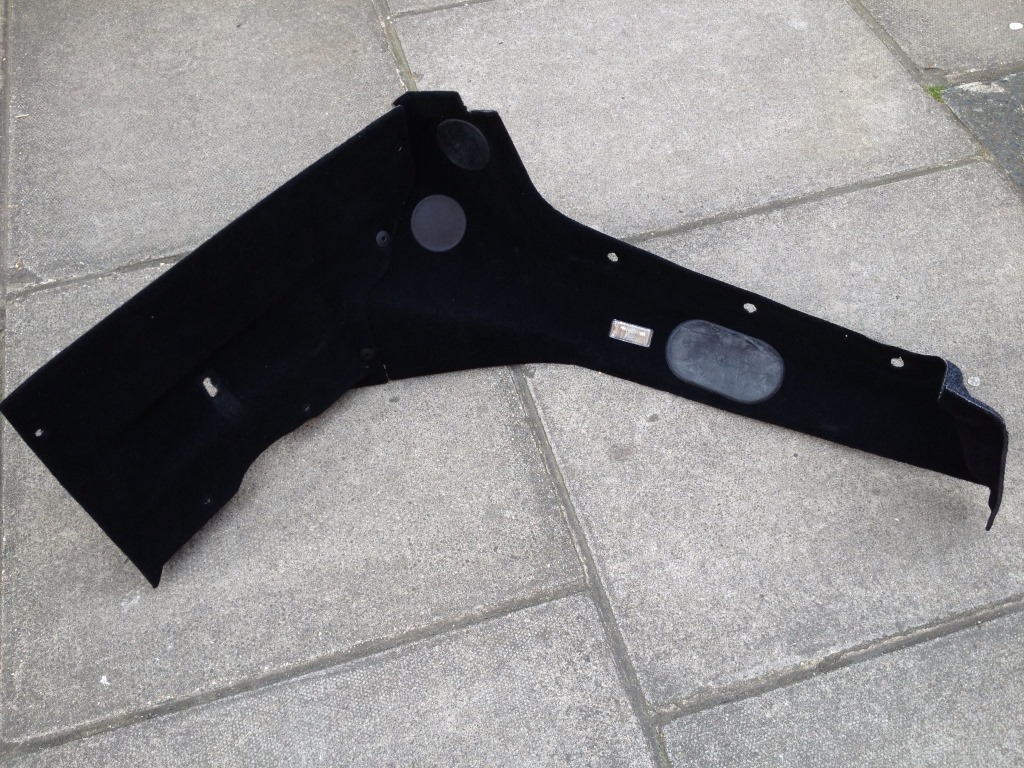
First of all, as for any electrical work, disconnect the battery using the cut off switch. In order to remove the solenoid, the first step is to gain access to the lock assembly. This is done by removing (in this order) the fuse box cover panel, the main rear carpet panel, and the left-hand side carpet panel (the one that contains the courtesy light). These are held in place by hex socket screws – make a note of which go where as screws of two different lengths are used. The left-hand side panel needs to be carefully prised free of the bonnet release lever and manoeuvred out of the trunk – do not forget to disconnect the courtesy light power supply.
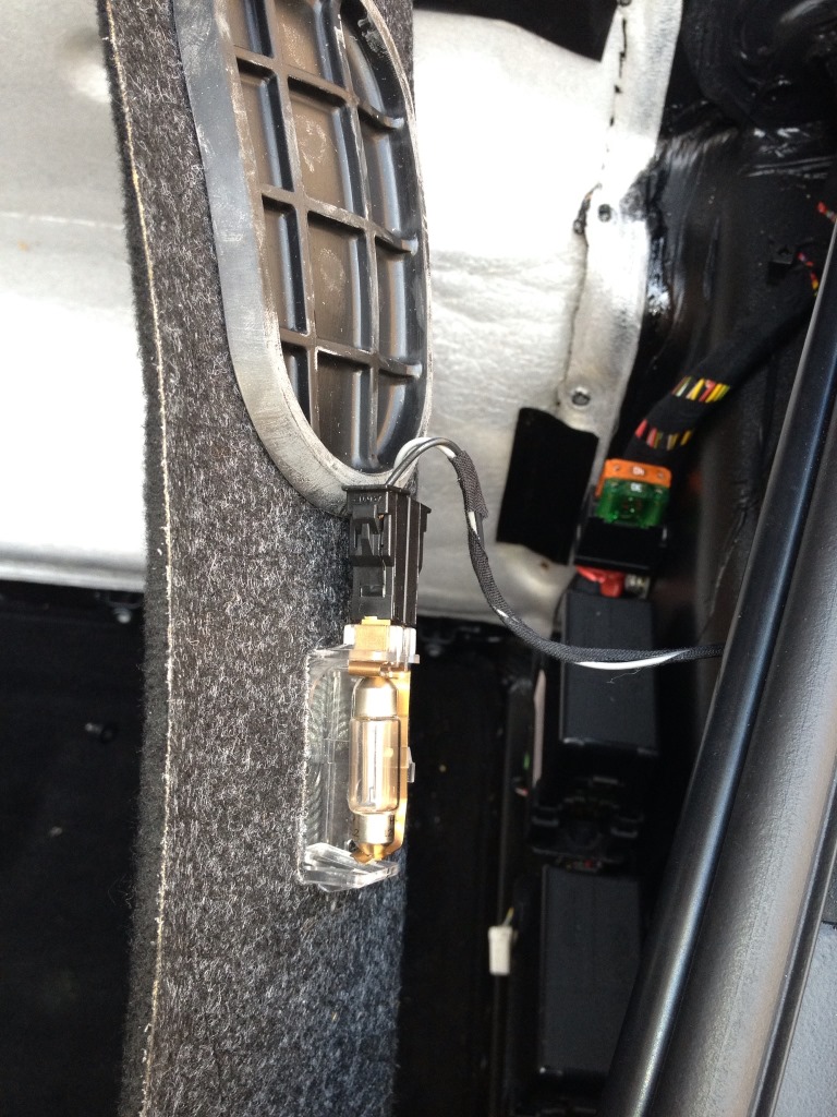
This is the panel once out of the car:
Before you proceed any further, now is a good time to check that the manual bonnet release is working. This is operated by pulling a handle in the cabin, located under the glovebox in RHD cars. You can now proceed to removing the solenoid from the lock assembly. It is held in place by two Phillips screws accessible from the top. You also need to unclip the plastic retainer that holds the metal hook in place, and remove the hook.
With the solenoid out of the car, you can start disassembling the female connector. This is a cross-section view from its data sheet:
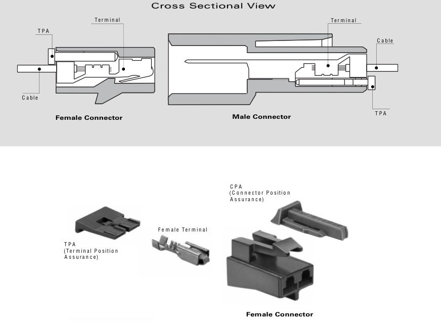
First the TPA needs to be removed, unclipping it with the tip of a small flat screwdriver. You then need to insert a thin metal instrument under the female terminal to release the metal catch that holds the terminal in place. The metal terminals can then be extracted. This is what you should be left with:
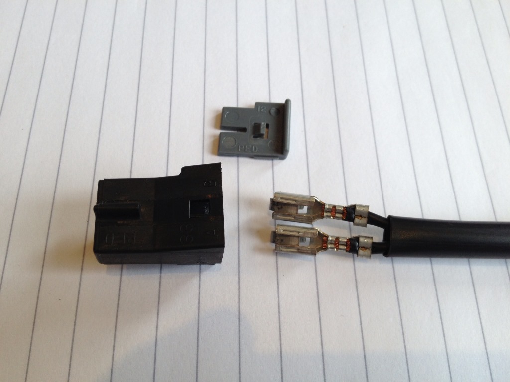
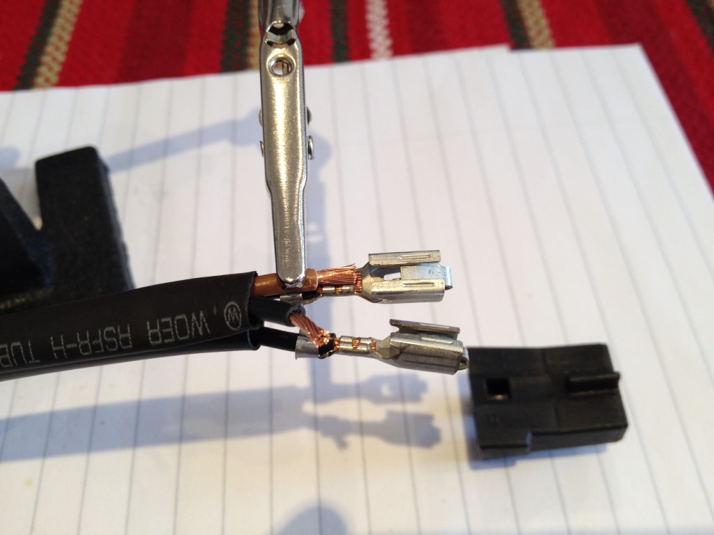
You can now solder a new wire on top of the crimp section of each terminal – an alligator clip to hold everything in place while you solder is very useful:
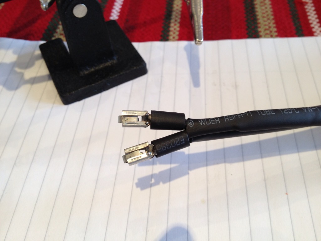
It is possible that the insulation of the original wires gets damaged during the soldering. This can be repaired by sliding a small section of heatshrink tubing over it and curing it (eg with a hairdryer).
The solenoid does not have a polarity (and both its wires are black) but our device does as it gets its ground from here, so you need to be careful with which wire goes where. The ground wire should be connected to the terminal that goes into the “B” position in the connector (which connects to the black wire on the wiring-loom side), while the control wire from our relay should be connected to the terminal that goes into the “A” position (which connects to the brown wire on the wiring-loom side) – look for the “A” and “B” stamped on the female connector housing.
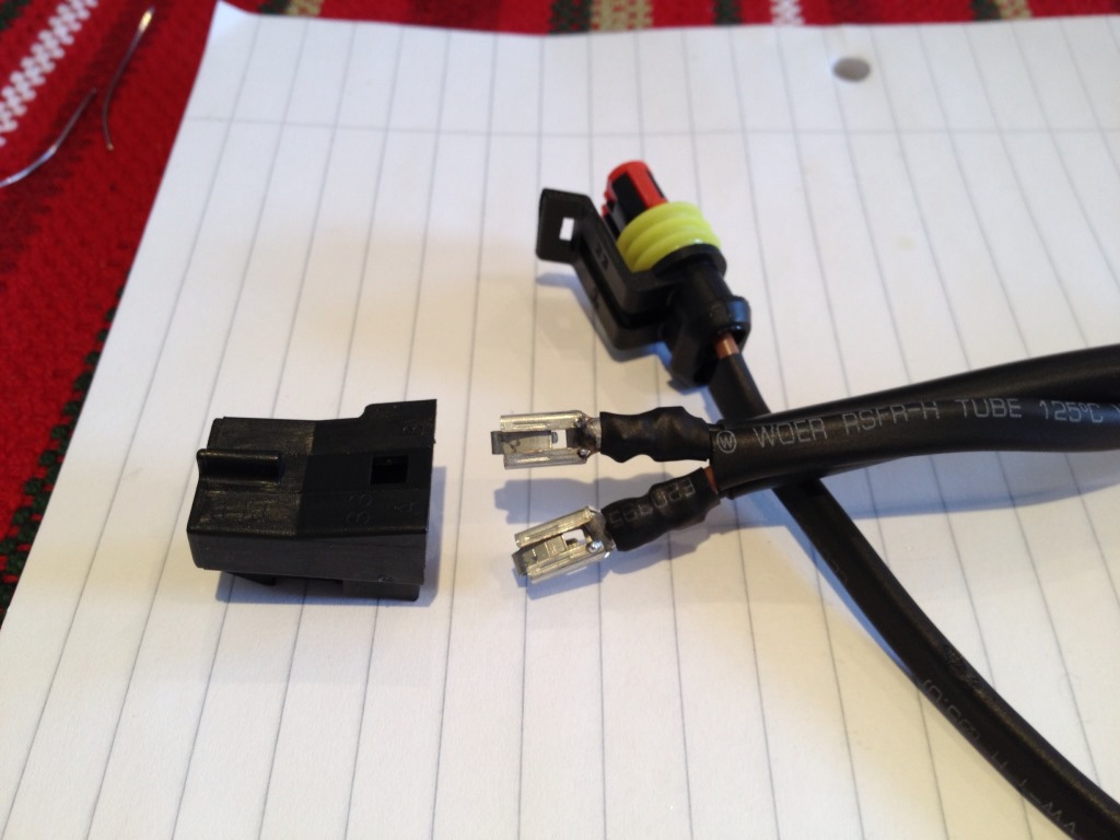
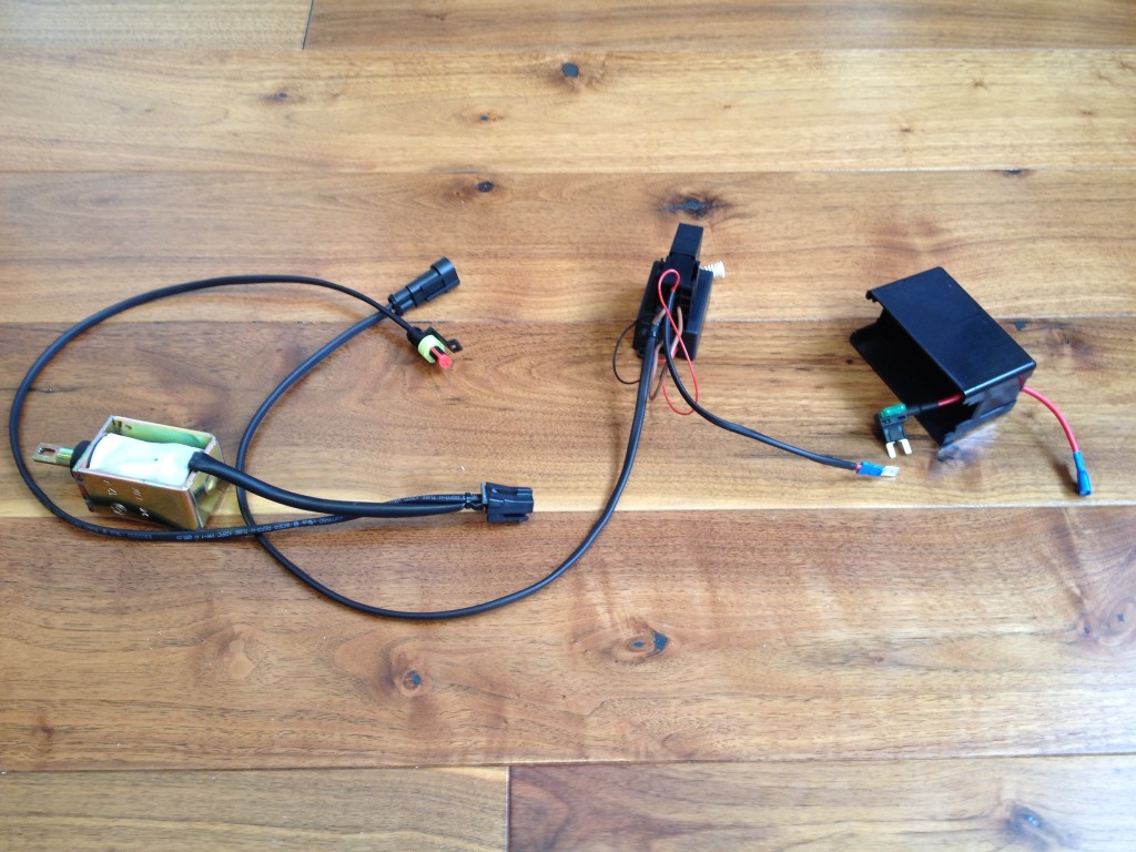
You can attach these new wires to the device directly but I preferred to insert a connector in the middle, to ease re-assembly. I used a SuperSeal male & female connector set but any appropriately-rated ones will do. (AV Note: I buy my Superseal connectors from 3 Way Components). This is a photo of all the components of the device just before reassembly into the car:
The solenoid needs to be reattached first, in a reversal of the removal procedure above. You can then reconnect the Metri-Pack connector and secure the wires in place with cable clips or wire-harness tape. I also chose to protect the wires with heatshrink tubing along their entire lengths.
The device itself sits nicely under the middle fuse box and can be attached using double-sided tape or Velcro.
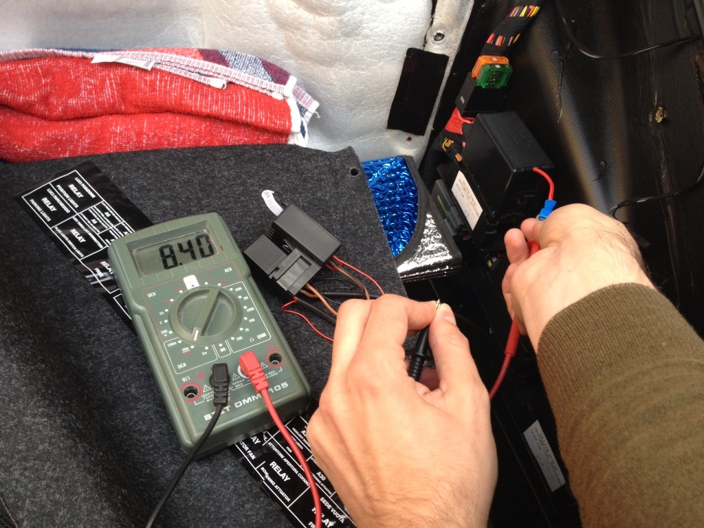
Finally, reconnect the battery and check absorption with a multimeter – I saw a 8.40 mA drain (do not operate the switch while you carry out this measurement).
I also checked the range with all the panels back in place and with the bonnet closed and found it to be approx 2 meters. One final remark – the bonnet opener will work even if the car is locked, but (at least on mine) doing so will trigger the alarm!
Here’s a quick video we made of the unit in action:
Other posts in this category: General Stuff
If you enjoyed this post why not subscribe to this blog for further updates? Simply enter your email address in the box at the bottom of this page. Your email address will not be shared.

A very comprehensive post, however, the bonnet release switch on my 2003 F1 coupe works without a key in the ignition- unlike the fuel flap release, which needs ignition on.
That’s very interesting – I will email you for some more details on your car. The car the control unit was fitted to was also a 2003.
Hi Aldous
My 2004 Modena is the same, ignition on is only required for the petrol filler release.
I think it’s only spiders that need ignition on for the front boot release. Probably a security measure