I decided that it would be a good idea to fit a unit so that I could control the exhaust bypass valves on my car independently of the Motronics. The main reason I wanted to do this was so I could force open the valves when sat in heavy traffic (I live in London and it is not unusual to be caught in a gridlock). My thinking is that by having the valves open the hot exhaust gases can escape more easily and reduce the amount of heat soak in the engine bay. Now that I have driven the car with the valves forced open I have discovered that the exhaust also sounds incredible when downshifting so I am definitely sold on the idea of being able to override the system.
There were a few choices available to me. Firstly the Capristo unit – it is undoubtedly well engineered but, in my opinion, is overpriced for what it offers. At the other end of the scale there is a unit offered for sale in the UK which is little more than cheap eBay remote relay and a few connectors – I don’t believe this is safe to fit to a car. In the middle of the market is the offering from Forza Componenti which is made by fellow Ferrari enthusiast Steve Bisel. Steve has developed a very nice kit and I was originally going to buy one from him. However, I wanted it slightly customised and after discussing with Steve we decided that it would be easier all round if I just made one myself. My solution is based on Steve’s kit and if you are not comfortable with electronics than I can recommend buying one of his kits off the shelf instead of trying to build one.
First of all we should examine how the valved system works. Both the 360 and the F430 have an exhaust valve in each tail pipe similar to the one pictured below.
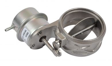
The valve is normally open and is controlled by applying a vacuum to the little pipe shown to the left of the picture – this causes the valve to close shut and prevents any gas from passing through. The different system layouts are explored at the beginning of this post but what is common to all systems is that when the valves are open the exhaust becomes more free flowing (and thus louder).
The vacuum applied to the valve is controlled by a solenoid similar to that pictured below. When a voltage difference is applied across the electrical terminals the vacuum supply is switched to the valve. The amount of voltage controls the amount of vacuum that is connected to the valve and in turn controls how much the valve opens – at 12V the valves are fully open.

The solenoid is permanently connected to the a fused 12V supply at one terminal and to the ECU at the other.

The ECU applies a voltage of between 0v and 5v at the other side of the soleniod which creates a voltage across the solenoid of between 7v and 12v. At 7V the valve is closed and at 12V fully open. The valves are not digitally operated and there is a transition phase between states to prevent them oscillating. The pattern has been expertly mapped out by fellow F430 owner Stefvan on Ferrari Life.
Clearly if one or both of the connections to the solenoid are interrupted then the valves will remain open and in fact some people simply disconnect the electrical connector from the solenoids to achieve this. Other people have interrupted the loom with a switch so they can control the operation at will. Neither of these methods is inherently dangerous so long as care is taken to protect the wiring to the ECU.
Aside from metering the voltage across the solenoid, the ECU also monitors the current draw. This allows it to check that the valve is operating correctly. On the F430 malfunctions are logged as errors P0475, P0477 and P0478 however they do not trigger a CEL. I am not 100% sure if the Capristo control unit triggers these errors, but know that all other solutions will. I set out to design a unit that would control the valves safely without triggering errors.
My design is represented in the schematic below:

Essentially I am using two changeover relays to interrupt the connection between the ECU and the solenoid. Instead of just breaking the connection I switch the ECU to a load resistor – this fools the ECU into thinking that it is still connected to the solenoid and prevents any errors from being logged.
There are a number of safeguards in the circuit. Firstly, both sides of my circuit are protected with a low 5 Amp fuse. In the event of anything going wrong these will blow immediately. Secondly, diodes have been placed across the relay coils. They are called Flyback Diodes and are there to protect from sudden voltage spikes when the relay coil is operated (Wikipedia has a good explanation). The relays are set up so they maintain the OEM circuit in their resting state – this means that on start up, and if anything fails, they will revert to how the was the car was set up at the factory.
It would have been possible to use a manual switch in the cabin to activate the relays however in my F430 there are no spare switch spaces and I didn’t want to run wiring through the bulkhead. I chose to use a remote control to activate my valves and sourced a cheap remote control unit from China (pictured below).
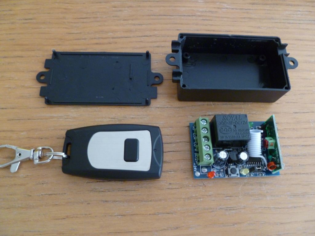
I checked that the remote control unit had a flyback diode already fitted but it would have been easy to solder one onto the board if needed.

Now trusting something like this is always going to be a bit of a gamble so I only use it to switch the earth to my main relays. I also wired it up so that when the relay is resting the circuit is open. That way if anything goes wrong the operation returns to the OEM state.
When sourcing the main relays it is important to choose ones that will cope with life in the engine bay – I chose heavy duty automotive relays rated at 40A. In order to make things easier I bought a pair of harnesses to fit the relays that already had a diode in place.

In order to connect into the wiring loom and couple of cables had to be made up to run between the soleniods and the box containing the switching circuit – one cable for each side of the car. Each cable needs four wires so I used 4 core automotive cable with each core 1mm² in size and overall diameter of 5.8mm. At one end I wired up a Male and Female 2-Way Junior Power Timer connector – this allows the cable to connect to the car loom and the solenoid respectively. The other end of the cable could be wired directly to the circuit but I wanted to be able to remove the box without taking the cables out of the car so I put in a 4-Way Superseal connector. I bought the JPT and Superseal connectors from 3 Way Components (who I can thoroughly recommend).
Since the cables are going to be placed close to the exhaust system I sheathed the cable with 6mm Vidaflex 111. The ends were finished with cloth loom tape and to help identify which cable is which I put colour markers at the connectors.

The length of the cables will be determined by the positioning of the control box but one definitely needs to be longer than the other.

Choosing the power resistors to fool the ECU was a little more involved. I measured the impedance of the soleniods to be 22 ohms and also observed the current draw when the valves were closed to be 0.58 Amps. This equates to a voltage of 13V which is commensurate with the operating voltage of the car when the engine is running. The power dissipated works out at about 7.5 Watts per side.
I initially used a pair of ceramic resistors rated at 20W each and foolishly mounted them inside my control box which was made of ABS plastic.

I had underestimated the amount of heat these would generate and after a long test run I was faced with a melted box…

In order to ensure this didn’t happen again I went back to the drawing board. I replaced the ceramic resistors with ones clad in an aluminium heatsink. I also remote mounted them on a custom bracket so they were in the free air of the engine bay. I selected to use Arcol HS25 which are capable of dissipating 25W at 25ºC. I also increased the resistance to 220 ohms in order to reduce the heat dissipation by a factor of ten.

I mounted the switching circuit inside a ABS plastic box. The box has the two 4-Way Superseal connectors that link to the cables going to the solenoids. I also used a third 4-Way Superseal connector to link to the resistors and a 1-Way Superseal to link to a ground wire. The box contains the two main relays, the remote control switch, the fuses and a screw terminal strip to bring it all together. The 4 core cables enter through rubber grommets whilst the ground and antenna wires pass through appropriately drilled holes. The components are held firm inside the box with 3M double sided foam tape.

I mounted the box behind the LHS engine cover, above the fuel tank. This avoids having to run cables past the F1 pump and is in a very cool part of the engine bay.

The box was stuck to the chassis using 3M Dual Lock. I had this left over from a project on another car where I used it to hold removable headlight covers in place – it is a very strong fixing. I also added a zip tie to provide a secondary mechanical fixing.

The RHS cable was very easy to attached to the solenoid and loom – all that’s needed is to remove the cover and plug it in. The cable was run to the LHS between the chassis and bumper.

The RHS was a little more difficult to get to. I tried to go in by removing the diffuser but the heat shield got in my way. In the end I removed the electrical connector to the rear lights and put my hand down between the vacuum tank and the chassis.

I was working blind but managed to disconnect the loom from the solenoid and plug in my cable. The RHS cable was fed into the same area and the two cables run up to the LHS fuel tank.

The resistors were mounted on a bracket that I quickly fabricated from 1mm thick aluminium sheet. This was fixed to the chassis using a pair of M6 bolts that hold a bracket for the cover trim. The earth was also fixed to a local earth point bolt using a brass ring terminal.

I have tested my unit over the course of approximately 300 miles. The first test I did was to force both ECUs to log errors by running the engine with the solenoids disconnected from the loom. I cleared these errors and then ran the car with my kit connected and in use. I checked both ECUs again with an SD3 an there were no errors. I am periodically checking the the ECUs to ensure that no errors arise. I am confident that switching the ECU onto a load resistor fools it into thinking that it is still connected to a working solenoid.

If you wish to build a kit for a 360 then it gets even easier as the resistors are not needed – the ECU does not log any errors if the valves stop working. The circuit diagram simplifies to the following:

The total cost of putting this kit together was a little over £50 and took a couple of hours – if you are comfortable with electronics then I recommend you build one for yourself.
Related posts:
- Ferrari 360 & F430 Remote Control Exhaust Valve
- Ferrari F430 Exhaust Manifold Change
- Ferrari 360 Exhaust Silencer
- Ferrari 360 & F430 Remote Control Exhaust Valve
- Converting a Ferrari F430 Exhaust to fit a 360
Other posts in this category: Engine and Drivetrain
If you enjoyed this post why not subscribe to this blog for further updates? Simply enter your email address in the box at the bottom of this page. Your email address will not be shared.

Good day, Aldous.
Great post. When we discussed the problem with the F430 logging DTC’s in the ECU, the load resistor was the choice we both made. I am incorporating a load resistor in my controller kit.
I am only using one load resistor … I am using a separate relay that shunts both of the solenoids to the single resistor. I found that a single resistor of about 300 ohms seems to work fine and at that resistance, the power draw is only 0.48 watt. With that low power draw, you may not need the external heat sink mounting and you may be able to install the load resistor inside the ABS case. The temperature rise may be entirely acceptable and this would be low. You might want to try that as it would make your assembly more simple. If you were to use two load resistors, you may want to increase the resistance to 400 ohms or so. I am using the Arcol HS10 series which is rated at 10 watts … clearly 20x more than to be expected if you choose the 300 ohm or higher. These HS10’s are much smaller than the HS25 and, of course, less expensive.
In my case, I am mounting it inside the aluminum enclosure with a dab of thermal compound under it to provide a good heat sink to the enclosure body. Works like a charm.
Just a word of caution for others who might be fabricating their own controller … be careful that if you intend to use an ABS plastic enclosure that it will begin to melt at 85 deg C. As Aldous pointed out, in a cool heat zone, this will be just fine. But if you install it in a zone with higher temps this can likely be a problem. I live in Arizona and on the 360 Modena, the temperature behind the engine bay panels quickly gets to 75 deg C on a moderately warm day. On a really hot day, the temperature can reach 90 deg C.
A die-cast aluminum (aluminium for those of you in the UK) enclosure is a bit more costly (like 2x to 3x the ABS cost), but still very affordable. And … the metal enclosure can also be a heat sink for the load resistor whereas the ABS will not.
Regards,
Steve
Hi Steve,
As we discussed via email, I do not consider combining the two ECU outputs to be safe. In the event of the voltage output differing between the two Motronics there is a risk of damage. I understand that you are changing your design to segregate the ECU output signals at all times.
Regards,
Aldous.
Aldous
Do you know if Steve has made that change to two resistors as I about to order one? Just curious as to why you didn’t go with his kit — was it because at that time he didn’t incorporate the resistors and you didn’t want to through those error codes?
Thanks
Alan
Hi Alan,
You’ll have to ask Steve where he is with the two-resistor design. However, if I recall correctly you have a 360? In that case you don’t need the resistors and could buy one of his kits without them.
I didn’t go with Steve’s kit as it didn’t have the resistors and I wanted the flexibility to do other things with the controller (which will be revealed in due course!).
Thanks,
Aldous.
Hi … the changes have been made. All kits now have two resistors. I have one of the older kits with no resistors.
I have a 2002 360. I am thinking of replacing the factory cats with Kinetix cats (180 cell) and a stage three Capristo muffler. I am sure that the exhaist note will be louder when the stock valves open, but at lower rpm, won’t the sound be as docile as the factory with the factory valves controlled by the ECU’s? I assume when the valves open at about 4k, I will simply enjoy a less restricted muffler. Am I wrong on this? Do you have any thoughts on these components? Both manufacturers claim an exact fit with stock. Thanks for you reply.
A stage 3 capristo is going to be loud, valves open or closed. I would recommend you hear a car in the flesh before buying!
I’ve not had any kinetix cats in front of me before but can recommend capristo products.
Steve, please let me know how I may contact you to discuss an order for one of these for my 360?
Hi Aldous,
It has been a while since we communicated. I thought I would add in something that have found over the last couple of years of making exhaust controllers.
I have found that vehicle ECUs are not sensitive to the resistance of the circuit when checking to see if the circuit is complete or not. IMO, the ECU is merely checking to determine if the circuit is either open or closed. If open, there is possibility of logging an error code. If closed, the ECU thinks all is well. This characteristic allows one to his higher value resistors which draw less current and thereby create less heat that needs to be dissipated. For example, if one were to use a common metal oxide 470 ohm – 3 watt resistor, the temperature rise of the surface of the resistor will less than 10 deg C. Barely warm to the touch and is less than 13% or the resistor’s power capacity. A typical resistor like this will only cost $0.25 or so at the local electronics store and could easily be contained inside the enclosure that you are using, not requiring an external heat sink to dissipate heat.
I have been successfully utilizing resistors such as this on my exhaust controllers. I use 5 watt resistors which provide additional capacity and the surface temperature rise is only barely perceived to the touch.
I thought I would give you my experiences so that others who wanted to make their own controllers can benefit.