This is a post I’ve been wanting to write up for a while but it’s taken time to find someone willing to make the investment in their engine and then we had to wait for their belt service anniversary to come around. However, the stars aligned and earlier this year we got the job done.
This piece of work is something I recommend to anyone who has a “keeper” 360 but many owners don’t even know about the benefits. In the race to the bottom, UK workshops don’t like to promote this service – some because they lack the skills to perform it, but mostly because it’s a job that is difficult to offer a fixed price that is attractive to the customer and still make money on (due to the time involved).
360 engines left the factory in Maranello timed up on scribe marks made on the camshaft during manufacture. Although the marks are adequate for the engine to run well, the best performance is made when the engine is timed up properly by adjusting the position of each cam individually so that the valves open and close as per the engine design. The difference between an factory set engine and properly timed one is small yet immeasurable. The engine will run a lot smoother and be a joy to drive – it is very difficult to set out in words.
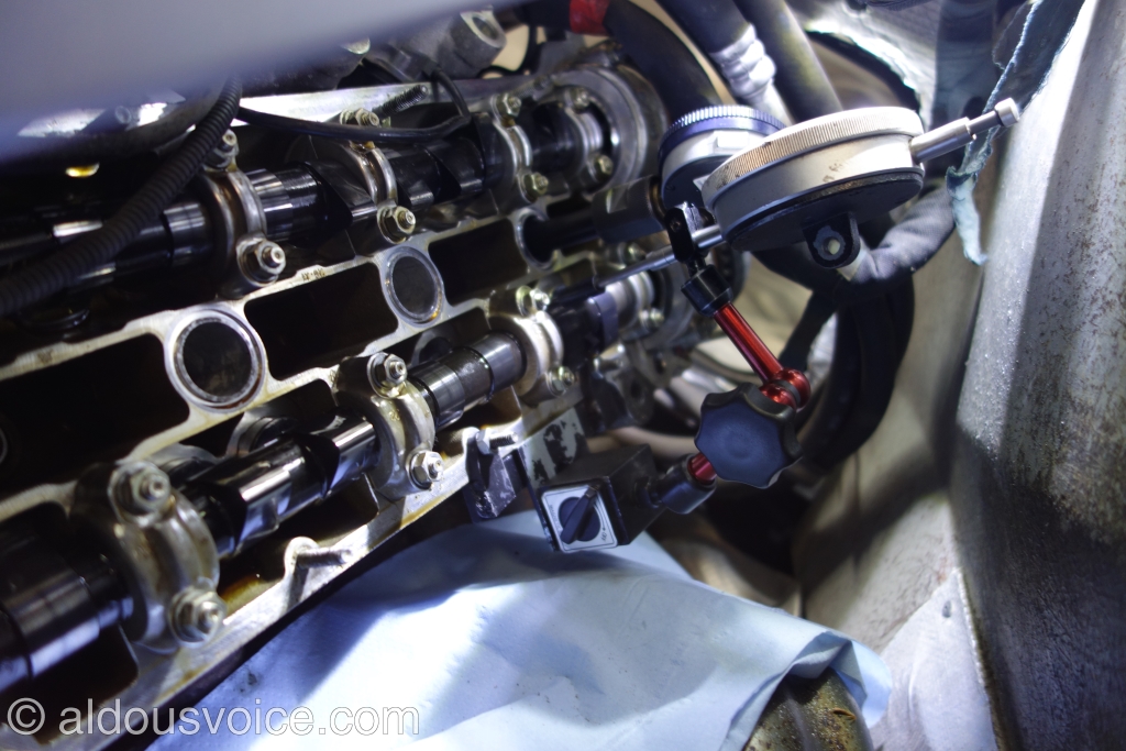
Before the adjustments can be made, the cam covers need to be off and the spark plugs removed. New timing belts need to be installed and the tension set (new tensioner bearings are also a good idea). Now is a good time to replace the cam seals and to remove the exhaust cams to inspect the variators. Access is through the firewall and the seats need to be removed.
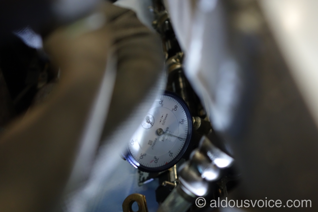
A DTI needs to be installed into cylinder #1 (I can wholeheartedly recommend the Hill Engineering TDC kit). As the picture below demonstrates, there’s not much room to work with (even more so with a spider roof cassette getting in the way).
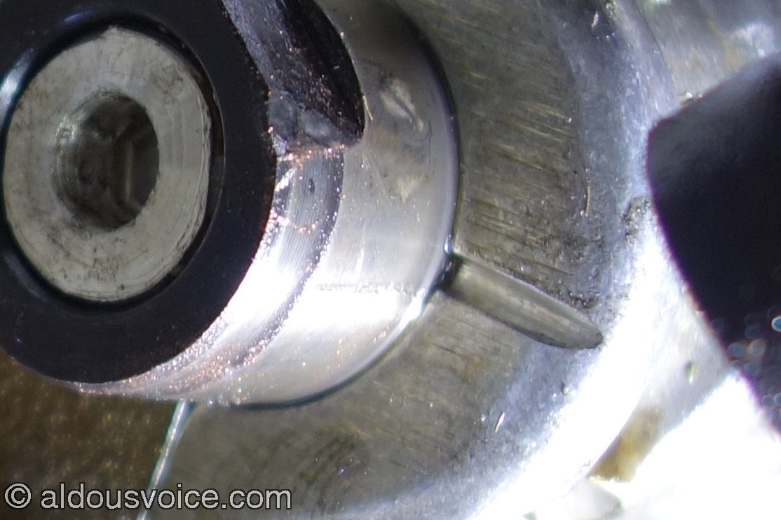
When cylinder #1 is at TDC before the start of the combustion stroke, the timing marks of the rear of the cams should all be aligned with the grooves on the cam caps. The scribe on the cam is just about visible in the following photo (click to enlarge).

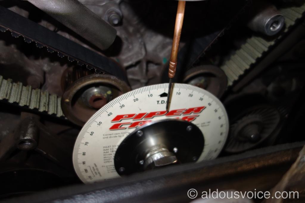
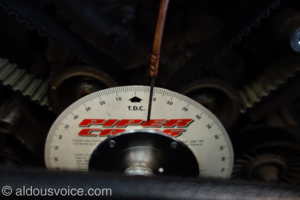
A degree wheel needs to be installed on the crank and set to TDC.
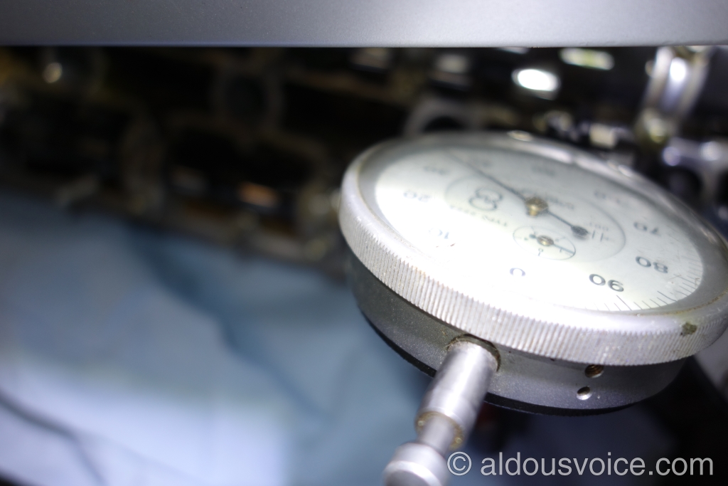
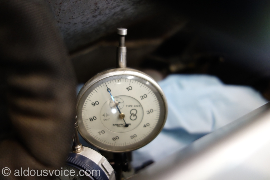
To measure the timing of the intake cam a DTI needs to be positioned so that the tip is resting on the bucket of one of the intake valves of cylinder #1. Note that the middle valve cannot be used as it has a different profile to that of the outers. This DTI needs to be zeroed in this position (apologies for the poor picture but the camera re-focused on the top of the gauge).
If we take a moment to think about the situation the engine is in, it should be straightforward to understand how the intake timing is measured.
- Cylinder #1 is at TDC before the start of the combustion stroke. The intake valves are closed.
- The engine is then rotated so that #1 piston completes the combustion stroke and is part way through the exhaust stroke (ignore what the exhaust valves are doing).
- At this point the DTI that is resting on the intake bucket should still read zero as the intake valves have not yet begun to open.
- The engine is rotated until #1 piston completes the exhaust stroke and reaches TDC.
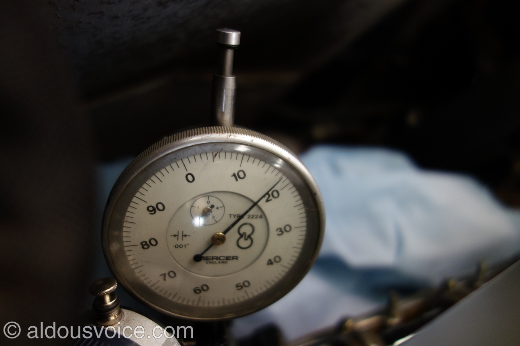
- At this point the intake valve will have started to open and the DTI resting on the intake bucket will have moved. It is this measurement that defines the timing. The valve should have moved downwards 1.66mm.
In this case, the valve had moved just 0.92mm which means the cam was opening the valves too late (note that the DTI in the picture below has moved counter-clockwise).
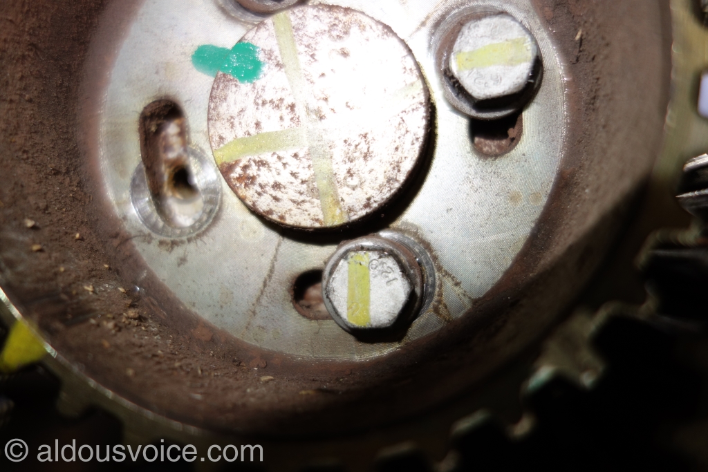
In order to rectify this the cam needs to be moved in relation to the crank. First the pulley wheels are locked in place. Note the green mark across the cam and pulley.

The pulley bolts are then loosened and the cam rotated in the correct direction (counter-clockwise in this case). The pulley bolts can then be torqued up and the timing checked again.
It is then a case of move and measure until the timing is correct. There is a 0.12mm tolerance on either side of the 1.66mm measurement which allows a small window to aim for.
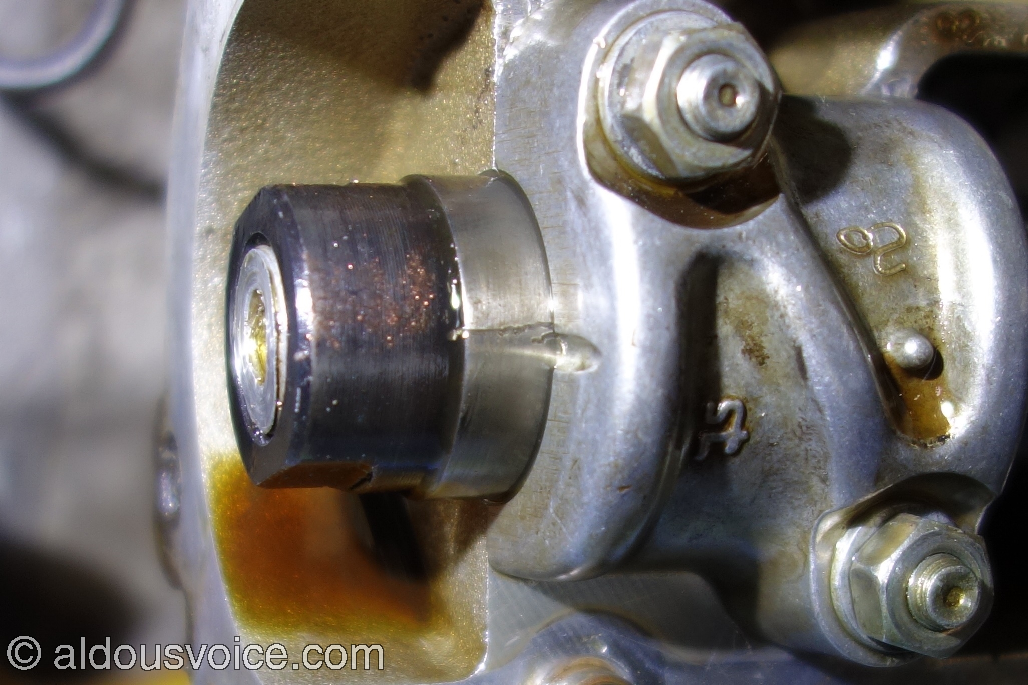
To give an idea of how much the cam had to be moved note the final position of the green mark and how far the pulley bolts have moved off their witness marks. There was nothing wrong with the running of this engine yet this cam was quite a few degrees out.
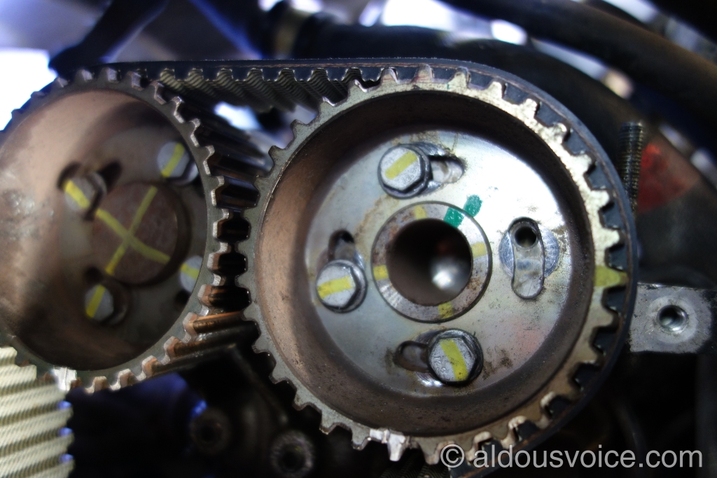
Turing attention to the factory mark, it can be seen (click the picture to enlarge) that it almost off the groove on the cam cap…
The exhaust cam is measured in a similar way. A DTI is placed so that the tip is resting on a exhaust bucket of cylinder #1.
The engine is then rotated until cylinder #1 is 9 degrees before TDC at the end of the exhaust stroke.
The DTI on the exhaust bucket is then zeroed.
Again, if we take a moment to consider the position the engine is in, the timing measurement should be easy to understand.
- Cylinder #1 is nearing the end of the exhaust stroke. The exhaust valve is closing but remains part open.
- As the engine is rotated further the piston finishes the exhaust stroke and begins the intake stroke.
- During this operation the exhaust valve fully closes.
- The DTI measures the travel of the valve as it closes. This distance should be 0.60mm.
In this case, the valve moved 0.18mm which means the cam was opening the valves too early.
As per the intake cam, the position can be moved relative to the crank by locking the pulleys and rotating the cam (clockwise in this case). Once the cam has been rotated it is a matter of measuring and repeating until the timing is correct. Again, there is a window to aim for – 0.08mm either side of the 0.6mm.
The following picture shows how far the cam had to be moved:
And here you can see that the factory scribe is off the groove on the cam cap…
Once the RHS of the engine has been timed it is then all repeated for the LHS side, using cylinder #8 as the reference.
Although it is straightforward to write out, performing the work is demanding not least as the consequences for getting something wrong can be disastrous. However, the results are a beautifully running engine…
Other posts in this category: Engine and Drivetrain
If you enjoyed this post why not subscribe to this blog for further updates? Simply enter your email address in the box at the bottom of this page. Your email address will not be shared.

Hi Alsous
I had mine done 2 years ago and your right the performance is amazing. I have pictures of the job in progress if it helps you viewers?
Please do share them
Amazing post. Is this only relevant for 360 engines ?
Hi Nigel – the timing is adjustable on many other Ferrari engines but the 360 was the last of the V8s that could be set up this way. The F136 engine (which was introduced with the F430) featured continuously variable valve timing on both the intake and exhaust. In effect, the car sets up it’s own timing.
reading this post with great pleasure. Can you pls advice what wuld be the cost of such a fine tuning. do I have to come to a specialized shopin the UK or can you recommand other good shops in Holland or arround, k rgds paul
I don’t have any recommendations for workshops outside of the U.K. – sorry.
However, any decent engine builder should be able to do this work for you.
Tks but how much do you estimate such a job will cost?
Nice piece Aldous! It didn’t realise that 360 cam sprockets are bolted on to the cams as opposed to the 355 which is pegged. I did this process on my 355 but it was a pain because to make adjustments on the cams you have to remove and refit the belts each time. You cant simply turn the cam until the lift is correct.
Great piece, Aldous. Hope to see more of this type.
I was very surprised to see (unless my eyes deceive me) that the factory scribed timing marks on the cam ends were so wobbly. Normally an important timing mark like this would be a very straight scribed line. What say you?
They are decidedly vague aren’t they?!
Great article!
My one question is what tool did you use to turn the cams to carry out the adjustment? As they do not have a hex on or any obvious place to get a tool on the cams to turn them.
I used an open ended spanner – there’s a flat on the back of the cams
If intake valves open at 10 degrees BTDC and exhaust valves close at 9 degrees ATDC, why did Ferrari suggest to zero the dial indicator at 9 degrees BTDC and measure 0.60 mm for the exhaust valves ?? If Ferrari wanted measure the start of the overlap, shouldn’t it be 10 degrees BTDC when you zero the dial gauge on the exhaust valves? Also, why doesn’t Ferrari give us a measurement at TDC for exhaust valve opening (like they do on the F355) Much easier to do at TDC instead of 9 degrees BTDC. Thanks for the reply !!
I really cannot comment on why Ferrari decided to reference the timing in this way. It is a question for the factory.
Thanks for your reply ! I was looking at how the timing is done on the F355 (similar engine) and I read that intake is done in the same way, but for the exhaust you zero the dial gauge at TDC and rotate until the exhaust valve closes to get a measurement. Is it correct in the 360 Workshop Manual to zero the dial gauge at 9 degrees before TDC, or does it make more sense to zero dial gauge at exactly TDC. (remember 9 degrees after TDC is when the exhaust valves close, while 10 degrees before TDC is when intake valves open. The 9 degrees before TDC do not mean a thing) Maybe the WSM got this wrong ? (I know that they one word is wrong in the timing table on page 34, it says exhaust close End BEFORE TDC 9 degrees , instead of AFTER TDC.) Thanks again for the reply !
Hi new to this site but very interesting reading thanks for taking the time very handy for 360 owners.regards John